diy solar

diy solar

General RV inverter/wiring install questions

yantruocmot

New Member
Joined
Feb 12, 2022
Messages
21
I am planning out an inverter install and solar expansion in our RV/Travel Trailer and have some questions and need help from those with more experience.

To give some high-level details on the plan. I have a 2000w Xantrex Freedom X inverter. Planning to install a hardwire Huges Watchdog suppressor that will then output to the inverter. The inverter will then connect to the power center and its built-in auto transfer switch will be used to switch between shore and inverter modes. It will also connect to a Victron Lync bus bar that will connect up all 12v items including the batteries, solar and 12v back to the power center.

I have the general layout and wiring sorted however wondering about some things and don't want to accidently fry some expensive hardware or wires.

Questions:
1. Shore power and battery charging, the freedom x does NOT have a charger so I was planning on using the lithium compatible power centers charger. When I know when running in inverter mode I need to shut the charger breaker. But when connected to shore power since this connects on the 12v side will there be any chance of weird surges or "looping" of the electricity that can cause anything to fry? if so how is this stopped?

2. I am planning to mount everything on the ceiling of my passthrough. The invert instructions say this is ok. I am putting them on a 3/4 thick plywood so that they will have more to grip onto. Should I leave this wood uncovered or is it ok to either paint or cover it with something? I assume thin carpet is not good as I think fire danger (even higher than just plain wood). What is the best material for this?

3. Any other electrical "loop back" gotch-ya's to be looking for? I already have breakers for the solar panels, and battery switch and 250amp T-fuse etc. and using Victron Lync bus bar. I can even add mega fuses in the Lync if that might help with anything.

Thanks ahead of time for the input/help! I just want to make sure I dont burn down or anything up!
 
I am planning out an inverter install and solar expansion in our RV/Travel Trailer and have some questions and need help from those with more experience.

To give some high-level details on the plan. I have a 2000w Xantrex Freedom X inverter. Planning to install a hardwire Huges Watchdog suppressor that will then output to the inverter. The inverter will then connect to the power center and its built-in auto transfer switch will be used to switch between shore and inverter modes. It will also connect to a Victron Lync bus bar that will connect up all 12v items including the batteries, solar and 12v back to the power center.

I have the general layout and wiring sorted however wondering about some things and don't want to accidently fry some expensive hardware or wires.

Questions:
1. Shore power and battery charging, the freedom x does NOT have a charger so I was planning on using the lithium compatible power centers charger. When I know when running in inverter mode I need to shut the charger breaker. But when connected to shore power since this connects on the 12v side will there be any chance of weird surges or "looping" of the electricity that can cause anything to fry? if so how is this stopped?
Transfer switch has shore input and inverter input. Wire a separate breaker box and outlet from shore power input. Plug your converter/charger into this outlet. It will only be powered when shore is plugged in.

2. I am planning to mount everything on the ceiling of my passthrough. The invert instructions say this is ok. I am putting them on a 3/4 thick plywood so that they will have more to grip onto. Should I leave this wood uncovered or is it ok to either paint or cover it with something? I assume thin carpet is not good as I think fire danger (even higher than just plain wood). What is the best material for this?
cement backer board.

3. Any other electrical "loop back" gotch-ya's to be looking for? I already have breakers for the solar panels, and battery switch and 250amp T-fuse etc. and using Victron Lync bus bar. I can even add mega fuses in the Lync if that might help with anything.
Does your inverter bond neutral and ground? Does your transfer switch do anything related to neutral ground bonds? You need to understand grounding. Filterguy wrote a 3-part PDF on grounding that includes how it works in an RV. You can find it in the resources section of this forum.
Thanks ahead of time for the input/help! I just want to make sure I dont burn down or anything up!
You're welcome!
 
Thanks for the input, I had forgotten to share that my power center is a WFCO 8740Lis. Its charger is built in, not separate or replaceable. It does have its own breaker.

It sounds like you're saying it better to have a separate charger that is totally outside of the power center on its own. Where its own connection when on shore power (that does not route through the inverter) and by having its own breaker and plug will isolate it from any possible loop?

Would an inverter that has a charger inside of it solve this issue, understanding that it would still require the built-in charger/converter to be disabled or disconnected?
You will be able to use that converter/charger. You may just have to change where its AC plug is plugged in. Those power centers have a pre-wired outlet on the back (which is connected to that breaker) that the converter plugs into. If need be, you can unplug it from there and plug into the outlet I described in my original answer; however, that may not be necessary.

Can you post a link to the power center specs/manual?

Are you wiring for 30a or 50a service?
 
...

Would an inverter that has a charger inside of it solve this issue, understanding that it would still require the built-in charger/converter to be disabled or disconnected?

I just looked up the power center model. It's for 30a service. This means you will have to wire up a separate breaker from your shore power inlet (same rating as the breaker the converter is connected to in the panel) and rewire the powercenter's built-in outlet to that newly installed breaker/box. It's not a difficult process.

If you choose to go with an inverter-charger, that would probably have a built-in transfer switch and would make your separate (discrete) transfer switch unnecessary. If you've already purchased the components, I would just rewire the outlet or change where the converter plugs in.

Don't be afraid to look over the power center and see for yourself. You're already talking about wiring your own electrical system, no point in being afraid to re-wire an outlet or unplug a plug.
 
The Xantrex Freedom X already has a built in 30a transfer switch, I do not have nor was I planning on any separate external transfer switch. Does this change the need to try and separately wire the charger? As I am not sure how I would do that considering its hard wired into the existing charger and not a plug in model (i.e. if it burns up or dies the whole power center needs to be swapped out, not just the converter.)

Here is a link to the power center - (Manual under downloads)

Here is a link to the inverter (12v/standard model) - (data sheets and manual are on right hand side downloads)

My original thought was that the built in transfer switch would block any loopbacks however not being 100% sure of that I wanted to ask as the 12v side of the converter would always be connected. I would assume that WFCO has isolated the 120v and 12v sides in some way just not sure. Or am I totally over thinking this?
 
The Xantrex Freedom X already has a built in 30a transfer switch, I do not have nor was I planning on any separate external transfer switch. Does this change the need to try and separately wire the charger? As I am not sure how I would do that considering its hard wired into the existing charger and not a plug in model (i.e. if it burns up or dies the whole power center needs to be swapped out, not just the converter.)
I find that hard to believe. These power centers are made to be serviced.
Here is a link to the power center - (Manual under downloads)

Here is a link to the inverter (12v/standard model) - (data sheets and manual are on right hand side downloads)

My original thought was that the built in transfer switch would block any loopbacks however not being 100%
The transfer switch will not stop the converter from being powered by the inverter load circuit if it [the converter/charger] is wired to the inverter load circuit.
sure of that I wanted to ask as the 12v side of the converter would always be connected. I would assume that WFCO has isolated the 120v and 12v sides in some way just not sure.
Yes the AC and DC sides are isolated in the power center. The issue to address is not about isolating AC from DC. It's about not creating a power loop/drain on your batteries.

Or am I totally over thinking this?

You're not over-thinking it.

With an auto-transfer switch that could drop to battery power at any time for any reason (regardless of where the transfer switch is) you need an automated way to make sure the converter is not part of the inverter load when the inverter is on battery power OR the converter needs to be powered outside of the inverter load circuit.

The inverter feeds the inverter load circuit whether on shore (AC pass through) or battery. If the inverter is on battery power and feeding the converter while the converter is pushing power to the battery, you've created a power loop in the circuit that will drain your battery fast.

Trying to rig a fix would be overthinking and/or stepping into jerry-rigging territory. Not a good idea.

Your options are:

1. Don't power the converter directly from the power center (I will almost gurantee this is achievable)

2. Get a different power center without built-in converter AND replace inverter with an inverter/charger

3. Get a different power center AND a separate converter/charger AND don't power the converter/charger directly from the inverter load circuit.

Options 1 and 3 both require a separate (small) breaker box, branched from your Shore power disconnect junction where you would either hardwire the converter to or wire an outlet to plug the converter into.

Option 2 means returning/repurchasing components (if you still can), but would be the least complicated when it comes to wiring your circuits.
 
While I cant return anything at this point I can sell it, I want to make sure I have this right.

If I went with option 2. I cant replace with any model that doesnt have any converter but I can either pull the wire for the breaker or just turn the breaker off in the power center for the converter. Then use the Xantrex Freedom XC (with a charger), then I wouldnt have to worry about any of the loops? https://www.xantrex.com/power-products/inverter-chargers/freedom-xc.aspx
You may be able to find a breaker-lock for the breaker, to lock it in the off position. I would NOT just "turn it off and forget about it" though.

Also note, that if you can "pull the wire for the breaker" that you are "unwiring" the converter. The line coming from the breaker is the AC "hot" for the converter. If you open up the panel (which you'll have to do in order to install breakers and wire the rest of your circuits), you'll see the converter's neutral going to the neutral bar and the ground going to the ground bar (white and green wires respectively). All you have to do is unwire those, extend and run them to a separate breaker powered outside of the inverter load circuit.

It will be simpler and less costly than selling your inverter for a loss and buying another more expensive inverter that has a component you've already paid for but aren't going to use.
 
Ok yep, that makes sense. I am thinking "outloud" here, so with that connected to its own breaker outside of the inverter but still sending power via the 12v side of the converter, that does not cause any possibility for a loop, right? Any other potential loops to think about as well, or is the charger/converter the main one?
 
Ok yep, that makes sense. I am thinking "outloud" here, so with that connected to its own breaker outside of the inverter but still sending power via the 12v side of the converter, that does not cause any possibility for a loop, right? Any other potential loops to think about as well, or is the charger/converter the main one?

Yes. Ground loops. Refer back to my original response where I asked about how the inverter handles neutral/ground bond and referred you to FilterGuy's PDF documentation in the resources section of this forum. Hang tight, I'll post a link.
 
Start here, it has links to all parts of his grounding documentation. Feel free to come back with questions. If I can answer them, I will. If not, we can call someone else over with more knowledge.

 
Last edited:
Took a little time to read all of those, thank you for sharing! Those made perfect sense and helped raise my understanding of grounding, something I have always wondered about (especially on AC) this helped!

I am leaning toward getting a new inverter charger, while I cant return the one I have I got it REALLY cheap in comparison to what they are going for now, and its still new. I believe I can get back at least what I spent. I found a charger version of the same thing for just a little more. That will allow me to simplify my wiring overall as well.

On question I do have about the grounding. In each example where solar was shown, the panels had a ground. Is that always the case and always needed? i.e. on a trailer? I currently only have one panel on the trailer but will be adding two more 200w, for a total of 600w between the three. I will need to look more close but I do not believe that the factory installed any ground on the one that came with the trailer. Now, does not mean they did it right, but want to ask/confirm what is right?

thanks again!
 
Is the trailer roof metal (stainless steel sheet metal)? How is the panel mounted to the roof? Does the panel have a metal frame? How/where is the charge controller mounted? Is it attached to metal? Is the battery negative grounded to the frame? If all of these are affirmative then it is adequately grounded.
 
No, roof is the rubber/EPDM type. It is wood truss, not metal at all in the roof. The panels are attached via what appears to be "Z" brackets. They do have aluminum frames. They plug into a solar "gland", assume its made by gopower and it is plastic as well. The charge controller (currently) is a GoPower 30amp PWM type, it is connected to wood as well, and no ground on it, this I do know. Just the input and output of the solar wires. I will be replacing that with a Victron 100/50 smart controller. I do plan to ground it and the inverter to the chassis ground that the battery neg will also be attached to.

Now that I think about it, unfortunately I cant confirm as its in the shop, it is possible that the neg wire from the solar charger goes directly to the chassis ground where the battery is also connected. So that would cover everything but the panels themselves.
 
No, roof is the rubber/EPDM type. It is wood truss, not metal at all in the roof. The panels are attached via what appears to be "Z" brackets. They do have aluminum frames. They plug into a solar "gland", assume its made by gopower and it is plastic as well. The charge controller (currently) is a GoPower 30amp PWM type, it is connected to wood as well, and no ground on it, this I do know. Just the input and output of the solar wires. I will be replacing that with a Victron 100/50 smart controller. I do plan to ground it and the inverter to the chassis ground that the battery neg will also be attached to.
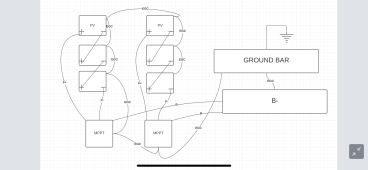
The panel frames should be grounded. If you examine the underside of the frame, you'll find a hole with a ground symbol on it. You need to run a wire from that to your RV chassis ground. If it's multiple panels, daisy chain them together and run 1 wire down to the chassis ground. I have 6 panels on my RV roof. Attached is a rough diagram of how my solar system is grounded.

Now that I think about it, unfortunately I cant confirm as its in the shop, it is possible that the neg wire from the solar charger goes directly to the chassis ground where the battery is also connected. So that would cover everything but the panels themselves.

That in itself would not ground the charge controller's case and would not ground the PV frames. According to NEC spec (this knowledge came from filterguy), to properly ground your solar system, the panel frame(s) must be grounded, the charge controller(s) must be grounded, and the solar DC circuit must be grounded.

If your charge controller's PV- and B- terminals have continuity, and your battery negative is grounded, then that takes care of the solar DC circuit.


In this diagram, EGC stands for Equipment Grounding Conductor. Note that my B+ bus bar is not depicted here. This is strictly to illustrate grounding. The P- and B- of the controllers are connected inside the controllers, therefore since the B- bus bar is grounded, the entire DC circuit (including the PV part) is grounded.

63BD8B68-F49A-4222-946A-B605FD094255.png
 
This is perfect, thanks! I will be picking up our trailer either tomorrow or next week. I will be looking for the ground wire on the existing panel and go from there.
 
Back
Top