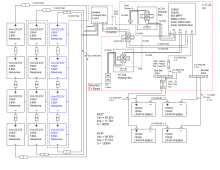
I have been toying with this subject for a while. I have watched all the videos from several people and I am still confused as to how to properly ground these solar systems. Please take a look at my diagram and let me know if the grounding is anywhere near correct and anything else you may spot. Thanks


You are using an out of date browser. It may not display this or other websites correctly.
You should upgrade or use an alternative browser.
You should upgrade or use an alternative browser.
Grounding Correct? Or Not?
- Thread starter LSC
- Start date
I would connect all the grounds (earth) to the 'grid power in' ground and there back to the correct ground in the main service panel. Not to any separate ground rod. I would have the solar panel frames attached to a seperate ground rod, not to the grid ground (earth) circuit.
MichaelK
Solar Wizard
Couple of items. First, I see no neutral to ground bond? Is that accomplished inside your Chins inverter, or should it be bonded outside? Second, it appears that the inverter has a voltage max of 100V? With four panels in series, have you determined what the voltage will be at your winter low? How cold is that?
I personally am not a fan of 100W 12V panels. How much would you be paying for those? I would replace those with four-six larger grid-tie panels, because their watts/$ is significantly lower.
Finally, I would revisit your wire gauges. 10 gauge out to the NEMA sockets seems extravagent, and 1 gauge for the battery connections appears only marginally acceptable. Besides just the current flow, thicker battery cables also help to minimize ripple current.
I would agree with Zil's comments.
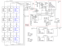
Thanks, I will post V2 after changes.I would connect all the grounds (earth) to the 'grid power in' ground and there back to the correct ground in the main service panel. Not to any separate ground rod. I would have the solar panel frames attached to a seperate ground rod, not to the grid ground (earth) circuit.
I wondered about the voltage. I read where it goes up with cold. At 25C (if I am interpreting it correctly) would be ~81V. It maybe gets down to -10F (windchill) rarely but mostly hovers around the teens to above 0. I am in CO. Is the voltage to close to 100? How far does it go up?With four panels in series, have you determined what the voltage will be at your winter low?
I have already purchased the panels, they will eventually go on the roof of an RV.
You don't think 1/0 at 3 ft. is big enough? Thanks
I was basing the awg on the max current the CHINS can put out which according to the manual is 25A for the AC Out. Is that the wrong way?10 gauge out to the NEMA sockets seems extravagent
MichaelK
Solar Wizard
You should be using the lower gauge wire from the inverter to the main electrical panel, because that is supplying all the current to all the breakers. Downstream of the breakers, you only need 12-14 gauge wire, depending on the size of the circuits, ie: 15A or 20A.I was basing the awg on the max current the CHINS can put out which according to the manual is 25A for the AC Out. Is that the wrong way?
Ok, thanks. I see what you are saying. Otherwise are the grounds now correct?You should be using the lower gauge wire from the inverter to the main electrical panel, because that is supplying all the current to all the breakers. Downstream of the breakers, you only need 12-14 gauge wire, depending on the size of the circuits, ie: 15A or 20A.
MichaelK
Solar Wizard
I see that you removed the ground wire leading from the inverter to the ground rod? It now appears that the inverter is not connected to ground at all? I also see that solar array is bonded to the rod? What exactly will your array be mounted on? In all that I've read about grounding, the solar arrays should be considered separate from the equipment grounding.Otherwise are the grounds now correct?
In the case of my own system, I have the steel arrays anchored in concrete, so they are naturally grounded that way. I do NOT have my combiner box connected to the array ground, I have it connected to my equipment grounding bussbar.
I think what you need to draw in is a bussbar specifically for ground, with everything except the solar array bonded to that bussbar. Then, the single contigious ground wire runs from that bussbar to the ground rod. It appears that you have a ground wire from the inverter to a bussbar directly under the 20A breaker labeled as "ACin Breaker Box". I think you should make that your primary above-ground earthling spot. All the above-ground items, like the ACout box, combiner box, ect should all be tied to that bar. Then, a thick 6 gauge ground wire running from that bar to the ground rod. That I believe will be code compliant.
I have 2 aluminum racks that are pre-made by eco-worth. Each rack holds 4 panels.What exactly will your array be mounted on?
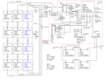
Ok, I think I got it. Just one last question. What awg should all these ground wires be going to the busbar. I made them 10 awg. I know 6 awg goes to gnd rod.I think you should make that your primary above-ground earthling spot
Attachments
MichaelK
Solar Wizard
The standard rule is the gauge of the ground wire is the same as the circuit it would be connected to. That is because is has to divert to ground the same amount of current that was flowing through the original wiring. So, if you have a 15A circuit wired with 14gauge wire, then the ground is the same 14 gauge. If the main electrical panel is fed with an 8 gauge wire, then the ground should be 8 gauge.Ok, I think I got it. Just one last question. What awg should all these ground wires be going to the busbar. I made them 10 awg. I know 6 awg goes to gnd rod.
Great, that is what I used, the other circuit wires are 10 awg as well, except for the one going to the gnd rod. Thank you so much for your help. I now feel confident in building this system.The standard rule is the gauge of the ground wire is the same as the circuit it would be connected to
MichaelK
Solar Wizard
BTW, how are you going to get the rod pounded into the ground? I used a 24" post pounder, paired with different lengths of scrap steel pipe. I first slid a piece of 6' pipe over the rod, and pounded it in 2'. I then switched to a 4' length of pipe, and pounded another 2'. Then 2' pipe, and finally the top end of the post pounder.
Nice drawing.
I would replace the ANL fuse with a Class T fuse for the Main fuse from the Bus Bar to the Chins 3000 for the batteries. Lifepo4 batteries have a high arc flash that an ANL fuse is not rated for...
The MRBF Terminal Fuse would also be a better fuse for each battery instead of the ANLs.
ANL fuses are good for Lead Acid batteries, but not so good for Lifepo4.
 www.bluesea.com
I would replace the ANL fuse with a Class T fuse for the Main fuse from the Bus Bar to the Chins 3000 for the batteries. Lifepo4 batteries have a high arc flash that an ANL fuse is not rated for...
The MRBF Terminal Fuse would also be a better fuse for each battery instead of the ANLs.
ANL fuses are good for Lead Acid batteries, but not so good for Lifepo4.
Blue Sea Systems - Innovative Electrical Systems — Built to last
Engineering high quality marine electrical components for safety, reliability and performance
www.bluesea.com
timselectric
If I can do it, you can do it.
- Joined
- Feb 5, 2022
- Messages
- 20,043
Not from the US , I guess?In all that I've read about grounding, the solar arrays should be considered separate from the equipment grounding.
Hired help!! ?BTW, how are you going to get the rod pounded into the ground?
Thanks. I see everyone using those. I was a little concerned about adding a higher value amperage because of the discharge current max of 140A. Would a 150A T fuse work?I would replace the ANL fuse with a Class T fuse
I have not heard of those. I will go find them. ThanksThe MRBF Terminal Fuse would also be a better fuse for each battery instead of the ANLs.
timselectric
If I can do it, you can do it.
- Joined
- Feb 5, 2022
- Messages
- 20,043
Not even close.The standard rule is the gauge of the ground wire is the same as the circuit it would be connected to. That is because is has to divert to ground the same amount of current that was flowing through the original wiring. So, if you have a 15A circuit wired with 14gauge wire, then the ground is the same 14 gauge. If the main electrical panel is fed with an 8 gauge wire, then the ground should be 8 gauge.
That would be a 3/0 grounding conductor for a 200a panel?
There are tables for sizing equipment grounding conductors.
Now you have me worried. Is there a difference I should know about?Not from the US , I guess?
Have you got a link to one by any chance? ThanksThere are tables for sizing equipment grounding conductors.
MichaelK
Solar Wizard
That is not correct. The standard wire leading from the ground rod to the main grounding buss is 4 gauge for 200A service.Not even close.
That would be a 3/0 grounding conductor for a 200a panel?
There are tables for sizing equipment grounding conductors.

/electrical-ground-wires-840064560-f3e982dbc913428492f26c22687ff673.jpg)
Residential Electrical Service Grounding Requirements
The earth ground ensures the safety of an electrical system—the key components are the grounding rod, grounding wire, and grounding clamp.
Last edited:
timselectric
If I can do it, you can do it.
- Joined
- Feb 5, 2022
- Messages
- 20,043
My point exactly.That is not correct. The standard wire leading from the ground rod to the main grounding buss is 4 gauge for 200A service.
3/0 was following your theory.
timselectric
If I can do it, you can do it.
- Joined
- Feb 5, 2022
- Messages
- 20,043
Have you got a link to one by any chance? Thanks
MichaelK
Solar Wizard
Are your purposely trying to cause confusion? That is really unprofessional.My point exactly.
3/0 was following your theory.
timselectric
If I can do it, you can do it.
- Joined
- Feb 5, 2022
- Messages
- 20,043
Absolutely not. I'm hoping that the OP gets the correct information. Electricity is dangerous, if improperly installed.
Every reference I have to awg of earth grounds list minimal 8 gauge. You are dealing with 25 AC amperes. 8awg will be fine, larger will not hurt. When you are plugged into the grid, your earth grounds must go to the main panel earth ground. That you have. When you are disconnected from the grid, all AC current references back to the inverter case. That you have.
At 24 volts you should be fine with 1/0 awg marine grade cable. That will carry 285 DC Amperes. You need better fuses than ANL for main battery fuse, and closer to battery positive. Fuse to protect the wire. I would fuse 1/0 marine grade wire at 250 amperes. Not those 100 amp ANL.
The purpose of grounding the solar panel frames is for lightning protection. That earth rod should not connect to the equipment. I am open to correction of this, just give me a link to relative national electrical code.
Controversial on internet-->There must be only one earth ground when connected to the grid. Do not connect the equipment to that rod.
Similar threads
- Replies
- 14
- Views
- 428
- Replies
- 1
- Views
- 481
- Replies
- 7
- Views
- 462
- Replies
- 1
- Views
- 95