Here are the screenshots of user manual. I guess it would accept single string hooked in both mppts and then paralleled.Yes but you need to turn on that mode in the config. Otherwise they could fight, if running in independent mode, because independent trackers may try to operate at different voltages
And “both MPPTs” may be the wrong way to express this but you probably understand what is going on.


You are using an out of date browser. It may not display this or other websites correctly.
You should upgrade or use an alternative browser.
You should upgrade or use an alternative browser.
Help required to estimate VOC of panel strings compatible with inverter
- Thread starter NSsolar
- Start date


zanydroid
Solar Wizard
The DC bridge jumpers address my concern since they should pretty reliably ensure the two inputs share the current, and I expect that they do something smart with matching the resistance into both sides
Your screen shot points to the settings config on page 72
Your screen shot points to the settings config on page 72
Hedges
I See Electromagnetic Fields!
- Joined
- Mar 28, 2020
- Messages
- 21,404
Its max output wattage is 4600 w
In that case about 10s more or less would be a reasonable amount of over-paneling.
If 7s meets minimum MPPT voltage when hot, possibly 7s2p, with the two strings of very different angle, e.g. 45 degrees or steeper, one facing East and one facing West. That gives more kWh/day from more hours operation.
Hedges
I See Electromagnetic Fields!
- Joined
- Mar 28, 2020
- Messages
- 21,404
I have 9 panels right now. So, what you mean is that I should bring down the 9 panels in series and put the -tve and +ve terminals of solar array with mpp1 and st same time with mppt2? In this way it would be safe having Isc above 26A? I'm understanding right?
Yes.
W
What if the DC jumpers aren't available? What could be the solution then?The DC bridge jumpers address my concern since they should pretty reliably ensure the two inputs share the current, and I expect that they do something smart with matching the resistance into both sides
Your screen shot points to the settings config on page 72
zanydroid
Solar Wizard
You can jumper it yourself in the same way. There is a safety and performance question, if you jumper it yourself the basic safety of making sure the current is shared (so one doesn’t get all of it) is achievedW
What if the DC jumpers aren't available? What could be the solution then?
If consistent resistance is important to max out performance / spread the load evenly then more research is needed. If you don’t need to share the current evenly to achieve goals, and the MPPT linking algorithm can compensate, then there isn’t much to worry about.
This isn’t an issue I’ve researched in depth. It is somewhat analogous to wiring parallel batteries for even drain. IE maybe cross wiring can help
One of my technician suggested me to buy one more panel to make it a series of 10 panels. The new panel should have Isc less than or equal to 13.8AYou can jumper it yourself in the same way. There is a safety and performance question, if you jumper it yourself the basic safety of making sure the current is shared (so one doesn’t get all of it) is achieved
If consistent resistance is important to max out performance / spread the load evenly then more research is needed. If you don’t need to share the current evenly to achieve goals, and the MPPT linking algorithm can compensate, then there isn’t much to worry about.
This isn’t an issue I’ve researched in depth. It is somewhat analogous to wiring parallel batteries for even drain. IE maybe cross wiring can help
He says, when in series, this panel will bring down the current of all panels equal to the lowest panel current thus, the inverter will be able to draw 11A and be safe as well, from Isc perspective. Does this make sense?
@Hedges
@zanydroid
Hedges
I See Electromagnetic Fields!
- Joined
- Mar 28, 2020
- Messages
- 21,404
When you connect PV panels in series, they should have similar current ratings.
A panel with Isc 13.8A (and maybe Imp around 12A?) will only contribute power up to that current level. It will reduce the power available at voltage of 10s.
But the inverter can pull down to lower voltage. It could draw the 13.89A to 15.75A Impp of the remaining 9 series panels, activating bypass diode of the 10th panel. This higher current would overheat the diode, possibly melting backsheet and breaking glass of the panel. There could be 1 to 2V forward drop through the diode, some 15W to 30W of power dissipation.
If the inverter allows paralleling two MPPT inputs, that is the solution.
Thank you for your helpWhen you connect PV panels in series, they should have similar current ratings.
A panel with Isc 13.8A (and maybe Imp around 12A?) will only contribute power up to that current level. It will reduce the power available at voltage of 10s.
But the inverter can pull down to lower voltage. It could draw the 13.89A to 15.75A Impp of the remaining 9 series panels, activating bypass diode of the 10th panel. This higher current would overheat the diode, possibly melting backsheet and breaking glass of the panel. There could be 1 to 2V forward drop through the diode, some 15W to 30W of power dissipation.
If the inverter allows paralleling two MPPT inputs, that is the solution.
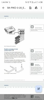
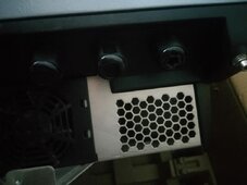
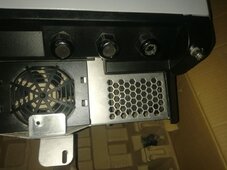
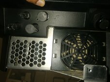
Here are pics of inverter's connections. I see two slots for PV inputs, suggesting it has two mppts. But I don't see any slots for DC jumpers which are shown in the manual for paralleling the mppts. I am attaching pic of manual too. So, how could make them parallel then?
Attachments
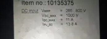
The datasheet of inverter says that when the mppts are paralleled, then the mppt range is from 265-800V. That's also written on the sticker of the Inverter. But sticker says nothing about current rating while in parallel mode. It only lists current rating of single mppt. See the pic of stickerWhen you connect PV panels in series, they should have similar current ratings.
A panel with Isc 13.8A (and maybe Imp around 12A?) will only contribute power up to that current level. It will reduce the power available at voltage of 10s.
But the inverter can pull down to lower voltage. It could draw the 13.89A to 15.75A Impp of the remaining 9 series panels, activating bypass diode of the 10th panel. This higher current would overheat the diode, possibly melting backsheet and breaking glass of the panel. There could be 1 to 2V forward drop through the diode, some 15W to 30W of power dissipation.
If the inverter allows paralleling two MPPT inputs, that is the solution.
Attachments
zanydroid
Solar Wizard
Are they inside? It looks like there are MC4 connectors on the outside for convenience.So, how could make them parallel then?
zanydroid
Solar Wizard
Is there a parallel option in the software UI?But sticker says nothing about current rating while in parallel mode. It only lists current rating of single mppt.
I don't know about it yet. The inverter isn't before me and it is uninstalled. These are mc4 connectors for PV inputs and there are two PV inputs. What I know is that it accepts two pv inputs but I don't know if it would allow parallel mode or not. The manual says it will. But I don't see this on sticker of the inverter. If it supports parallel operation, then the sticker should have current rating of upto 22A like it talks about voltage range of 265-800V.Is there a parallel option in the software UI?
They are outside the inverter and like growatt solis etc, these are connections for PV (MC4)Are they inside? It looks like there are MC4 connectors on the outside for convenience.
zanydroid
Solar Wizard
I meant, are there terminals inside, that the MC4 on the outside lands on.They are outside the inverter and like growatt solis etc, these are connections for PV (MC4)
The lack of specs on the unit is worrying. Not sure how to derisk that without booting it up or calling someone responsible for the unit (distributor or manufacturer)
This makes sense but I don’t think I would do it given the downsides. Downsides are:Does this make sense?
All panels will get dragged down. That is probably a smaller panel, and all other panels will be dragged down to behave as if they were smaller. This happens across all lighting conditions
So does the case Hedges talks about where the extra panel is bypassed. This could happen if something covers the panel, or if the panel drags the string down enough that the MPPT a bypasses it.
Hedges
I See Electromagnetic Fields!
- Joined
- Mar 28, 2020
- Messages
- 21,404
Or if the inverter simply keeps pulling more current, reducing voltage. The maximum power point could be at the lower voltage of 9s, and there may not even be a local maxima to make the dumbest of MPPT stop higher.
I would assume it was going to overheat the diode and cause damage. (Safer than assuming otherwise.)
But only under full sun.
I would assume it was going to overheat the diode and cause damage. (Safer than assuming otherwise.)
But only under full sun.
Hedges
I See Electromagnetic Fields!
- Joined
- Mar 28, 2020
- Messages
- 21,404
Thank you for your help
Here are pics of inverter's connections. I see two slots for PV inputs, suggesting it has two mppts. But I don't see any slots for DC jumpers which are shown in the manual for paralleling the mppts. I am attaching pic of manual too. So, how could make them parallel then?
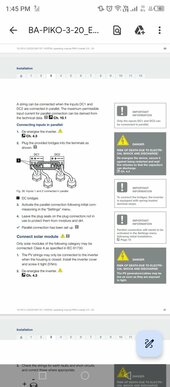
"Plug the provided bridges into terminals as shown"
That would be inside the inverter, just remove cover (with no panels attached and no AC connected, until done.)

Dear @Hedges
I'm using this inverter for grid feeding only. Haven't attached batteries or utility load with this one. Only purpose of this inverter is to share with the grid whatever it produces.
Isc rating of this inverter is 27A

My panels have Isc of 15.21A.
I have 14 panels at my disposal. I want to put 7S2P. I have tested single string of 7S which gave a voltage of 270-280V under load (max 3500W).
Since, the inverter can only generate 6000W, with 7S2P, would it remain under specs? Considering voltage to drop to 260, the PV current should be 6000÷260 = 23A
Will the inverter be okay with this 7S2P configuration Or it will harm the charge controller?
zanydroid
Solar Wizard
The MPPT is not guaranteed to operate at Vmpp. It can operate at lower voltage. Note that rating sticker also says 7000W max solar input.Since, the inverter can only generate 6000W, with 7S2P, would it remain under specs? 6000÷260 = 23A
Or it will harm the charge controller?
Might need to bite the bullet and buy extra inverter if the inverter and panels from matching generations are not stocked in your market. I think I said earlier in the thread that you’re looking at inverters matched to the previous panel generation (lower current)
Actually, all the inverters in our market are having same ratings of Isc as I have shared about. I won't like to go for a test, rather would like to buy another inverter. Thanks for your inputThe MPPT is not guaranteed to operate at Vmpp. It can operate at lower voltage. Note that rating sticker also says 7000W max solar input.
Might need to bite the bullet and buy extra inverter if the inverter and panels from matching generations are not stocked in your market. I think I said earlier in the thread that you’re looking at inverters matched to the previous panel generation (lower current)
Similar threads
- Replies
- 3
- Views
- 139
- Replies
- 2
- Views
- 161
- Replies
- 9
- Views
- 375
- Replies
- 5
- Views
- 263
- Replies
- 31
- Views
- 1K