diy solar

diy solar

Help!!! Smoke during top balancing

I would recheck all the connections and you can also swap the cell location to see if the reading will follow.
 
Can you ohm out connections all the way from cell terminal to BMS PCB?
I would guess extremely high contact resistance, megohms or essentially no contact in the harness so BMS input current upsets its voltage readings.

Given DMM readings of cells looks OK, what swapping would do is just jiggle wires and remake screw connections. If these had been believable readings, then swapping would possibly show issue follows cell.
 
I would recheck all the connections and you can also swap the cell location to see if the reading will follow.
Can you ohm out connections all the way from cell terminal to BMS PCB?
I would guess extremely high contact resistance, megohms or essentially no contact in the harness so BMS input current upsets its voltage readings.

Given DMM readings of cells looks OK, what swapping would do is just jiggle wires and remake screw connections. If these had been believable readings, then swapping would possibly show issue follows cell.


I swapped cells 2 and 3 and here’s the new readings
 

Attachments

  • 00B82144-806D-437A-AEF1-CB46D988AC50.png
    00B82144-806D-437A-AEF1-CB46D988AC50.png
    302.6 KB · Views: 12
Suggestion to OP, once you have BMS connected please upload clear pictures for us to look at and verify that it is hooked up correctly.
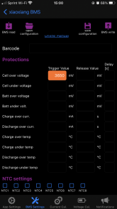
As requested ;) thanks budd, this is the main one I need to set yes?
 

Attachments

  • 67FF6349-A2D0-45D1-8A8A-A2461E87990C.png
    67FF6349-A2D0-45D1-8A8A-A2461E87990C.png
    154.9 KB · Views: 9
Do you think it’s a problem with the crimping on the balance leads or the blue B- leads ?
It really sounds like there is a connection problem somewhere. Do you have a crimp tool and crimp connectors (for the balance leads)?
 
It really sounds like there is a connection problem somewhere. Do you have a crimp tool and crimp connectors (for the balance leads)?

Yes I crimped them myself I’m going to take it off and redo them and send photos, the exposed metal was super small and the ring connectors I got are for 14-16 guage wire bc I needed a 5/16 ring

The openings to the blue are way too big for the wire

I had some smaller red one that were appropriate for the wire size but the ring was too small

Install Bay Vinyl Terminal Ring Connector 5/16 Inch 16/14 Gauge 100 Pack Blue - BVRT516 https://www.amazon.com/dp/B005V9V27...abc_EN29P364N77APKWE0AZX?_encoding=UTF8&psc=1
 
It really sounds like there is a connection problem somewhere. Do you have a crimp tool and crimp connectors (for the balance leads)?

Except the problem is likely in that tiny connector at the BMS PCB.
Different kind of terminal and crimper.
 
Yes I crimped them myself I’m going to take it off and redo them and send photos, the exposed metal was super small and the ring connectors I got are for 14-16 guage wire bc I needed a 5/16 ring

The openings to the blue are way too big for the wire

I had some smaller red one that were appropriate for the wire size but the ring was too small

Install Bay Vinyl Terminal Ring Connector 5/16 Inch 16/14 Gauge 100 Pack Blue - BVRT516 https://www.amazon.com/dp/B005V9V27...abc_EN29P364N77APKWE0AZX?_encoding=UTF8&psc=1
I'm not sure about the vendor you purchased from, but all that I am aware of have used m6 size for the terminals, and 1/4 inch should be perfect (for the battery end of the balance leads). I am not familiar with the Overkill BMS, but most vendors use 20 or 22 awg wires with JST connectors (.1 inch, or 2.54 millimeter spacing).

These are what I use, but you do need a heatshrink crimper die.

If you only have a regular crimp tool for nylon connectors, these should work

Home Depot or Lowes might have some in stock as well, now that you know what to look for.
 
Last edited:
Yes I crimped them myself I’m going to take it off and redo them and send photos, the exposed metal was super small and the ring connectors I got are for 14-16 guage wire bc I needed a 5/16 ring

The openings to the blue are way too big for the wire

I had some smaller red one that were appropriate for the wire size but the ring was too small

Install Bay Vinyl Terminal Ring Connector 5/16 Inch 16/14 Gauge 100 Pack Blue - BVRT516 https://www.amazon.com/dp/B005V9V27...abc_EN29P364N77APKWE0AZX?_encoding=UTF8&psc=1
Color code for crinmp connector:
Yeallow: 10 ~ 12 AWG
Blue: 14 ~ 16 AWG
Red: 18 ~ 22 AWG
You can fold the conductor over itself or solder it.
 
A bad crimp at the ring terminal should present as low voltage not high.
Just to be sure I'd walk the pins at the bms end of the harness.
Anyone else feel like translating that?
 
If one connection being bad is presented as low cell voltage, the adjacent cell will be high voltage.
Could be floating, could be tugged by nA input current of electronics.

3.146 + 2.892 + 3.889 + 3.31 = 13.237
13.237 / 4 = 3.31 V per cell
 
A bad crimp at the ring terminal should present as low voltage not high.
Just to be sure I'd walk the pins at the bms end of the harness.
Anyone else feel like translating that?
Yes, that's what I was thinking as well, I also thought about maybe wires crossed or shorted (i.e. wires attached to the wrong cell, etc).

But I'm not sure how the BMS calculates voltages per cell, a bad crimp might show as low on the cell it is supposed to measure, and then high on the next cell?
 
There is a way to check a wire harness from one end, rather than measuring ohms end to end.
If your DMM has a diode check scale, check from single wire of harness to ground on PCB. Reverse polarity and check again.
Typically IC inputs will show 0.7V diode drop for at least one polarity. If "overload" in both directions, no contact.
 
If one connection being bad is presented as low cell voltage, the adjacent cell will be high voltage.
Could be floating, could be tugged by nA input current of electronics.

3.146 + 2.892 + 3.889 + 3.31 = 13.237
13.237 / 4 = 3.31 V per cell
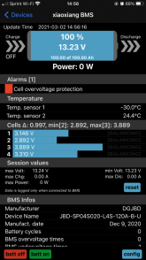
Yes, all the voltages add up to the reported battery voltage, I noticed that as well.
 
Yes, that's what I was thinking as well, I also thought about maybe wires crossed or shorted (i.e. wires attached to the wrong cell, etc).

But I'm not sure how the BMS calculates voltages per cell, a bad crimp might show as low on the cell it is supposed to measure, and then high on the next cell?

BMS could use a mux to take a series of single-ended measurements relative to negative terminal. Or it could take differential measurements across adjacent pair of sense leads. Those would load the signals differently, but typically inputs are high-impedance CMOS. Switching mux can charge-share into floating inputs.

Another forum member did have a similar problem, which he solved by redoing connections inside harness connector. I think the pins had slipped out of the housing.

I prefer big stuff I can put a screwdriver on. Or at smallest, 0.1" pitch connectors. Even those require a special crimper to do well.
Much of what I designed used 0.1" dual row IDC connectors on 0.050" pitch ribbon cable.
 
I bought better connectors more suitable for my balance leads and I’ll reattach tomorrow and report back - thank you again guys
 
Was able to get it charging in series, cell 2 got up to 3.6 so I switched back to parallel, then retested cell 2 and only getting 3.38 volts.

Why would cell 2 show 3.6 in series and then reduce in parallel ?


What’s interesting is that in series - cell 2 climbed drastically from 3.5 to 3.6 quick. Something is not right with these batteries or I must have damaged them.
 
Then to make matters worse, when I had them in series I was about to disassemble to go back to parallel, I accident touched a busbar on the main battery negative to the positive of cell 2 , big sparks ruined two of the screws that screw into terminal, I’m fucked ,I just wasted $500
 
Back
Top