diy solar

diy solar

Solar Generator Help

ki0x18

New Member
Joined
Nov 29, 2021
Messages
6
Location
Wichita, KS
Please bear with me since I’m relative new to solar

Soo I’m trying to run my garage/shop from solar.

The equipment that I have is:

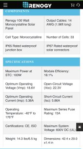
12-100 Watt Renogy Solar panels
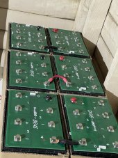
6- 12 volts 150Ah Lifepo4 from battery Evo
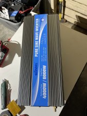
4000 watt gliden inverter
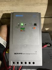
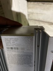
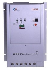
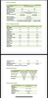
40 amp Renogy Mppt tracer (old model)
Plenty of wire from 22ga to 0/2

My ideas is to Build a 24v system with:
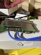
(3) 8S2P battery configuration for 24v with a 150ah bms from killers solar (3)

Im try to run mostly my lights (led)
and outlets for few 120v tools like:

-DEWALT table saw 15 amp 1200 watts
-shop vac 10am 1200 watts
-Heat gun 1200 watts 10amps
- bartery chargers (most of my tools are battery operated)
-usb chargers
- maybe a 1500 watt space heater
-led lights 60watts and ring cameras
- mini fridge (about 50-100 watts)
-chest freezer (60-150 watts)

My questions are:

What would be the best layout for my 12 panels for 24v array (ground mounted for easy access/maintenance)

What size wire/fuses should I use for the battery bank?
6-12v 150ah (2000watt hours) each
2 in serís for 24v, 3 in parallel for 450Ah

What size wire for my panel?
Should i use a combiner box?
Panels would be no more than 25 ft from garage/shop

I though about going with a 48v all in one system but alrededor had most of the parts order so that could be an upgrade later on if I nee more
Power

Any help/advice would be really appreciate? Thanks?
 

Attachments

  • E1200A70-4A62-44B8-913B-0B0B65B8C0B0.jpeg
    E1200A70-4A62-44B8-913B-0B0B65B8C0B0.jpeg
    183.4 KB · Views: 5
  • image.jpg
    image.jpg
    114.9 KB · Views: 6
  • image.jpg
    image.jpg
    120.5 KB · Views: 6
  • image.jpg
    image.jpg
    163.5 KB · Views: 5
  • image.jpg
    image.jpg
    125.8 KB · Views: 4
There is a lot to cover here.

First thing I notice is that your charge controller might be a little small. 1200W of solar on a 24V system gives up to 50A charge current. But you have a 40A charge controller. 40A at 24V can at most take advantage of 1060W when the batteries are at about 26.5V. Then again, it would be a rare day to get much more than 1060W out of 1200W of panels so getting a bigger charge controller may not be as useful as it seems. So after all of that, see how the 40A controller works for you. If it's always maxed out, consider a 50A controller.

Before anyone can offer the best option for wiring up the 12 panels (xSyP) you need to post the full specs of the panels and the charge controller. You want to keep the combined Voc of the panels, adjusted for your coldest possible temperatures, below the max PV input voltage of the controller. You do need enough panels in series so the Voc is at least 32V so the charge controller can actually charge your 24V batteries.

You will want a combiner box and fuses if you end up with 3 or more parallel strings of panels. But that's TBD yet.

A 4000W inverter on 24V requires pushing 4000W / 24V / 0.85 = 200A. Luckily that is just right for your 2/0 (not 0/2) wire (assuming your wire is high quality pure copper stranded wire with 105ºC rated insulation). So you want to wire your batteries with 2/0 wire. You want the wire between the batteries and the bus bars to be 2/0. And the wire between the bus bars and the inverter to be 2/0. You will want a 250A MEGA fuse between the inverter and bus bars. You will want a 250A Class T fuse at the battery positive lead.

Between the bus bars and the 40A charge controller you want 8AWG. But 6AWG might be better, especially if you might upgrade to a 50A charge controller. The 6AWG will of course still work with the 40A controller. You want a 50A breaker between the bus bars and 40A charge controller.

None of this addresses whether any of it actually meets your power needs. You should fill out the energy audit so you can be sure.


Im using the Renogy 100watt 12v


For the charge controller I’m using this one


Attachments

  • CC9AF886-9002-4387-9250-EE6689D3B049.jpeg
    CC9AF886-9002-4387-9250-EE6689D3B049.jpeg
    35.9 KB · Views: 5
  • 1C945892-CEE2-4718-90B7-DB7233984645.jpeg
    1C945892-CEE2-4718-90B7-DB7233984645.jpeg
    245.5 KB · Views: 5
  • DAB67B33-7D86-43AD-AF8F-4E54F6089C4B.jpeg
    DAB67B33-7D86-43AD-AF8F-4E54F6089C4B.jpeg
    281.2 KB · Views: 5
With a Voc of 22.3V and a max input voltage of 100V you will want to put your panels in 4S3P. You also have the option of 3S4P and 2S6P. I would choose 4S3P unless you have a bunch of shading issues to deal with.

4S3P gives a total Voc of 89.2V. If you live in a place where the temperature ever gets below 5ºF (-15ºC) then the Voc will get over 100V and that's bad. So if that is a possibility then you will need to setup your panels as 3S4P instead.

Either way you will need a combiner box and a fuse/breaker on each of the 3 or 4 strings.

I did just notice that the specs for your charge controller state a max of 800W of solar when used at 24V. That makes little sense to me since it can handle 40A output. I have no experience with Renogy (lots of problems with them can be found on this forum) so I don't know what it can really handle. But you should look into that. You either need to only use 8 panels instead of 12 or you need a better charge controller that can handle 1200W.
 
So you want to wire your batteries with 2/0 wire. You want the wire between the batteries and the bus bars to be 2/0. And the wire between the bus bars and the inverter to be 2/0.
So I should series connect (2) 12v with 2/0 wire and then parallel connect all (3) 24v with 2/0 also?
 
It would be better to build (3) single 24v battery bank and connects in parallel with 3 bms’s or single 24v batter bank with one bms
 
Back
Top