diy solar

diy solar

Help with dual Xantrex SW 5548 installation

G.W. Mad Scientist

New Member
Joined
Mar 27, 2023
Messages
109
Location
Oklahoma
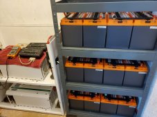
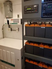
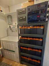
I have installed two SW5548 inverters that I had bought over 10 years ago. My question is when I turn one inverter on it comes on hums inverts and makes power just fine the second inverter when I turn it on it comes on with a very loud click with a hum it also inverts and produces power just fine however a relay is coming on when I turn that inverter on trying to power something. I thought I reset it back to factory specs and it still does it any members familiar with these Trace inverters know what's normal for these when you first turn them on? Is there a way I can look into it and see if there's something enabled that's turning a relay on in the programming? I'm going to use them strictly as backup inverters to the grid tie system. I don't really want a relay powered on all the time being an extra draw. Unfortunately when I bought these two they were open box and both the manuals were missing. They are Nos. Thanks in advance for any insight about this GW.
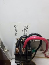
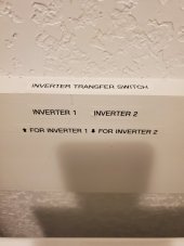
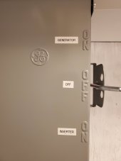
 

Attachments

  • 20230301_213621.jpg
    20230301_213621.jpg
    231.9 KB · Views: 7
  • 20230328_231154.jpg
    20230328_231154.jpg
    122.2 KB · Views: 8
  • 20230327_234948.jpg
    20230327_234948.jpg
    129.5 KB · Views: 8
Last edited:
I thought I reset it back to factory specs and it still does it any members familiar with these Trace inverters know what's normal for these when you first turn them on?
I'm somewhat familiar with its predecessor, the Trace SW, and from I have seen they are essentially identical.

Honestly I've never used the "factory reset" button but I can say that anytime the Trace loses DC power it resets to factory specs.

I can't tell from your description what exactly is going on (it's not you it's me...) but it does sound like something is out of line since they are acting different.

You might power it down on the DC side and see if the behaviour persists. I've got several paper manuals in my possession and I really need to get one into a copy center and have digitized.
 
Are you connecting these with series stacking for 120/240vac?

Do you have grid power on ACin ports?

SW5548 has no flash so when battery power is removed all user setting are lost and they revert to factory defaults when battery power reapplied.

The newer SW5548plus units do have flash and retains user settings.
 
I'm somewhat familiar with its predecessor, the Trace SW, and from I have seen they are essentially identical.

Honestly I've never used the "factory reset" button but I can say that anytime the Trace loses DC power it resets to factory specs.

I can't tell from your description what exactly is going on (it's not you it's me...) but it does sound like something is out of line since they are acting different.

You might power it down on the DC side and see if the behaviour persists. I've got several paper manuals in my possession and I really need to get one into a copy center and have digitized.
 
Thanks for the reply, and yes I believe the trace inverter is the exact same as the Xanax it's just a revision difference hence later the inverter the higher the revision. I believe these are 4.3 revision, I did disconnect the DC I also went into the settings and there's a reset in the settings as well. I did that to no avail I'm starting to think that maybe the relay clicks but doesn't really turn on. When I power the unit down I don't hear the relay click off. I'm wondering if it's just a glitch or a ghost in the system in that one inverter. Maybe it triggers the relay upon turn on but doesn't really hold it on as if it just glitches and momentarily Powers the relay for just a brief second when powering up. I had a set of the sw4024s before these two inverters and I can't remember if they made a noise when they powered up or not it's been so many years ago.
 
Are you connecting these with series stacking for 120/240vac?

Do you have grid power on ACin ports?

SW5548 has no flash so when battery power is removed all user setting are lost and they revert to factory defaults when battery power reapplied.

The newer SW5548plus units do have flash and retains user settings.
No they are not in series or stacked and I do not have grid power going into them they are completely separate from one another. For now they're more or less a giant back up power system, which remains in the off position with no DC current to them until they're needed. Then only one inverter is turned on and the breaker box is transferred to it instead of the grid. Second inverter is strictly a backup for the first one, Charging of the battery Bank is handled by a separate Argus 48 volt rectifier, powered from 120v ac , the inverters are wired to be inverters only and only one at a time can power the t240 transformer. The second one backing up the first should that inverter fail. Through a transfer switch. I'm wondering if it could just be a ghost in the system so to speak and that one invertermaybe just for a second trips the relay but doesn't actually hold it on when it's powered up. But perhaps upon powering up the system glitches clicking the relay but not truly holding it on? Neither inverter was programmed to do anything and they shouldn't hold programming because they're always in the off position unless being used and when I say Off they are DC disconnected.
 
Last edited:
Through a transfer switch. I'm wondering if it could just be a ghost in the system so to speak and that one invertermaybe just for a second trips the relay but doesn't actually hold it on when it's powered up. But perhaps upon powering up the system glitches clicking the relay but not truly holding it on?
Do not understand this statement, other than when you say transfer switch it raises a red flag.

These inverters synchronize their frequency, phase, and AC voltage to applied AC input. When using a parallel or series stacking cable inter-connect they will lock sync appropriately to each other when there is no AC input to inverters.

Neither inverter was programmed to do anything and they shouldn't hold programming because they're always in the off position unless being used and when I say Off they are DC disconnected.
These inverters have no AC input power supply to power internal electronics or AC pass-through relays. Controller, display, and transfer relay power is always taken from battery supply.

Just be aware the inverter factory default setup is max charging bulk current. Stupid default, but it is what it is. Bulk charging current should be the first thing you set when you apply DC input to inverter to prevent too much charge current for given battery AH size. They lose any user setup parameters when battery power is removed.

Without battery power the transfer relays are always open to AC inputs. No battery present, no AC input pass-through to AC output port.
 
I see so are you thinking I need to go into the inverters and disable the bulk charging? Is it possible when I turn it on it's turning on a relay to try to charge the batteries? These inverters have no AC input whatsoever, and they are completely separate from one another, one only backs up the other thru a manual transfer switch which is integrated in the inverter module case then goes to yet another transfer switch on the wall which allows me to send inverter power or generator power from my power room to my main breaker box and on that box there is a interlock that's either grid tie or backup power from the power room.
 
Calling the internal relay a transfer switch is not precisely correct. AC input to AC output pass-through relay is more precise.

When AC input shows up, the inverter will gradually adjust its AC phasing and voltage to match AC input before closing pass through relay. This takes 10 seconds to up to a minute or two depending on the difference in AC input frequency to inverter running frequency. You will hear the pass through relay clunk closed when sync is achieved.

There is a rather unusual hookup that may serve your desire.

You can connect the output of the backup inverter to the AC input of the active inverter. You can use the Generator AC input on active inverter if you want to leave the AC1 input for grid input or generator.

You can leave the backup inverter off so it provides no AC output fed into the active inverter AC input. You can use the backup inverter at any time and it will pass through the second inverter to its AC output.

With this setup you can actually run both inverters and the first one will add it output power to the power created by second inverter so you can have a 120vac output load on second inverter up to twice each inverter power capacity. The first inverter will be setting the AC frequency/phase/AC voltage in this case.

Set AC input limit current on active inverter to the amperage output limit of the first inverter.
 
Last edited:
No I wasn't calling that internal relay a transfer switch and I was curious about running one inverter through the other helping it without having to actually have a parallel cable but I opted not to do that. this is what I'm calling the internal transfer switch. It's not internal to the inverter it's internal to the inverter case. this case was made to mount two inverters in and you can stack another section and actually do three inverters and three phase. but the case transfer switch completely transfers it around the inverter. There is no AC input to either inverter the transfer switch has been rewired to be one inverter or the other with no AC input at all to either, the second transfer is literally an AC transfer switch on the wall after the inverter transfer switch, that selects inverter power or generator power. Not sure how that got confused but I apologize if I didn't word that good enough I guess a picture is a thousand words.
 

Attachments

  • 20230217_011219.jpg
    20230217_011219.jpg
    77.6 KB · Views: 2
  • 20230326_164000.jpg
    20230326_164000.jpg
    71.5 KB · Views: 2
  • 20230326_164526.jpg
    20230326_164526.jpg
    63.9 KB · Views: 2
  • 20230326_162116.jpg
    20230326_162116.jpg
    46.6 KB · Views: 2
The main reason I did it the way I did was my house is so efficient I can easily run the whole thing on one inverter and transfomer, the second reason was just plain simplicity I see problems with the inverters not wanting to phase together problems with running two inverters together either as 240 volt or 120 volt and then issues with the generator running through them Etc so I opted to make the system very simple no programming required NO phase locking needed it's inverter one or inverter 2, they do no charging or syncing with a generator however the original issue was when inverter one is turned on there is a loud click sounds like a relay comes on inverts just fine but I'm not sure if it's Phantom and just briefly on or actually holding on a relay, when inverter 2 is turned on completely separate of course makes no noise other than slight hum and inverts just fine as well.
 
Last edited:
Calling the internal relay a transfer switch is not precisely correct. AC input to AC output pass-through relay is more precise.

When AC input shows up, the inverter will gradually adjust its AC phasing and voltage to match AC input before closing pass through relay. This takes 10 seconds to up to a minute or two depending on the difference in AC input frequency to inverter running frequency. You will hear the pass through relay clunk closed when sync is achieved.

There is a rather unusual hookup that may serve your desire.

You can connect the output of the backup inverter to the AC input of the active inverter. You can use the Generator AC input on active inverter if you want to leave the AC1 input for grid input or generator.

You can leave the backup inverter off so it provides no AC output fed into the active inverter AC input. You can use the backup inverter at any time and it will pass through the second inverter to its AC output.

With this setup you can actually run both inverters and the first one will add it output power to the power created by second inverter so you can have a 120vac output load on second inverter up to twice each inverter power capacity. The first inverter will be setting the AC frequency/phase/AC voltage in this case.

Set AC input limit current on active inverter to the amperage output limit of the first inverter.
RCinFLA:
Would that scenario (adding an identical unit to the AC in) work with two Schneider Conext SW4024s? Schneider has discontinued "stacking" support for the SW series. I'm already AC/DC coupled off-grid to one SW4024 - I've considered adding a discrete panel with another SW - but I like your "unusual hookup" idea.
How would another unit affect AC coupling in the downstream unit? Total AC output capacity? Is there a particular software setting? Load share/shave/etc?
Example given: Offgrid Scenario
SW4024A AC out ----> AC in SW4024B (ac coupled) AC out -------> Main Panel <--------- 240 out from PV micros
Both inverters would be fed by the same battery bank.
Thanks.
 
RCinFLA:
Would that scenario (adding an identical unit to the AC in) work with two Schneider Conext SW4024s? Schneider has discontinued "stacking" support for the SW series. I'm already AC/DC coupled off-grid to one SW4024 - I've considered adding a discrete panel with another SW - but I like your "unusual hookup" idea.
How would another unit affect AC coupling in the downstream unit? Total AC output capacity? Is there a particular software setting? Load share/shave/etc?
Example given: Offgrid Scenario
SW4024A AC out ----> AC in SW4024B (ac coupled) AC out -------> Main Panel <--------- 240 out from PV micros
Both inverters would be fed by the same battery
 
Back
Top