diy solar

diy solar

Help with the little things!

Urge38

New Member
Joined
Mar 18, 2023
Messages
217
Location
London Uk
Hi Their Folks

I am slowly getting there with my build, and I was hoping I could pick a few brains to ensure I am on the right path when it comes to the little things like cable size, isolation switches and breakers.

here are my calculations.
Schneider XW inverter, capable of 12,000 W for 60 seconds
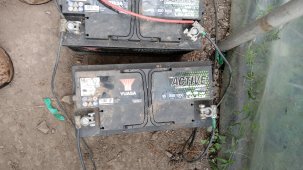
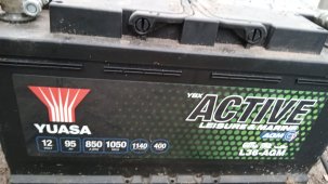
I have three, 5kw rack batteries (total 15kw) with 100a bms each at 48v (each with their own breaker built in on the batteries)

I figured. for the cable, 250amp cable will be the minimum for my needs, 250amp x 48v = 12000 w ????? am I on track???
I was going to go with some 70mm cable (I am in the UK) (2/0 AWG) depending on where you read up, the amps varies as to continuis amp carrying capacity.

Do I need isolation switches from the batteries to the inverter ??? one on each leg or just the positive????

Do I need a Bracker between batteries and inverter????

For now, I am concentrating on the batteries to inverter connections
 
I figured. for the cable, 250amp cable will be the minimum for my needs, 250amp x 48v = 12000 w ????? am I on track???

One does not need to size wires for surge ratings. You should only count on surge ratings for very brief excursions above max continuous like when you start an electric motor.

I was going to go with some 70mm cable (I am in the UK) (2/0 AWG) depending on where you read up, the amps varies as to continuis amp carrying capacity.

The insulation rating of the wiring determines the current rating.

Do I need isolation switches from the batteries to the inverter ??? one on each leg or just the positive????

The batteries have breakers, so I would regard that as sufficient.

Do I need a Bracker between batteries and inverter????

Most tend to prefer a single fuse or breaker to protect the single (+) wire connecting the battery bank to the (+) terminal. The battery breakers may meet this need.
 
Insulation, determines voltage and heat rating.
Conductor type and size, determines current rating.

I think both of our answers are incomplete.

Conductor type, size and insulation determine current rating.

Bare solid copper 10awg wire can carry at least a couple hundred amps. No, not a good idea or desirable in almost all situations, but it's the insulation wrapped around that wire that establishes the rated current.

How do we select wire for a given current? We select it based on the gauge, insulation rating and voltage drop.
Bare conductors can carry higher current because they can dissipate heat quickly.
Yes, there's a lot of factors that can affect the current carrying capability.
Like a 200a BMS with parallel 6 gauge wires.
When the conductor is only 8" long. There's very little voltage drop. And the silicone insulation can handle a higher heat range.
But, this is not a general use case. It's a dedicated pushing the limits case.
Insulation is chosen for its ability to contain a level of voltage. And survive a level of heat. Without suffering damage from either. And in most cases, also its ability to resist physical damage.
And of course cost is always important.
Heat is the enemy of efficiency. And should be avoided whenever possible.

And now I have lost my train of thought.
And am just rambling. lol
 
Could do 3 parallel of 35mm²
I'd say you could probably get away with something similar. However, I was incorrect. 4/0 is about 120 mm²
That means 3*35 is undersized. You could do 4*35, but that's a bit rediculous. I'd rather do 2*75 or 3*45 (I clearly don't know what exactly is available in metric, is 45mm² a common size?)

You'll want to pay extra attention to get all 3 identical length and excellent crimps. Their 4/0 spec is overkill, just like the math says.

Here in the uk 95mm is not hard to purchase.

Only I am NOT saying I am correct, but all my calculations had me at 75mm maximum.

I am wondering where you read the Schnieder needed 120mm ???

I would rather one thicker cable as opposed to two or three thinner cable.
 
would rather one thicker cable as opposed to two or three thinner cable.
I depend on solar full time.
But I ‘play’ with solar, too, as long as it meets my needs.

I wicked overcable battery to inverter cables, generally. While percentage-wise the ‘cost’ is absurdly different for larger cable, when measured in pizzas or going out to dinner (both of which most people don’t even think about the cost of doing) it’s really not significant on the grand scale.

Years ago I bought 2/0 battery cables for a 1200W inverter. Several upgrades later (four?) and I haven’t had to buy new cables due to needing a larger gage. Plus, I can rest assured that nothing to do with cabling is going to ever get hot.

Schneider is probably pre-anticipating certain people and is eliminating that variable for customer satisfaction. They won’t be getting hot.
 
Here in the uk 95mm is not hard to purchase.

Only I am NOT saying I am correct, but all my calculations had me at 75mm maximum.

I am wondering where you read the Schnieder needed 120mm ???

I would rather one thicker cable as opposed to two or three thinner cable.
I don't know which model of XW you have but here's a screenshot of the manual for the 8548. The 6848 (US split phase model) is the same.

I'd also rather one single cable over smaller cables in parallel.

Screenshot_20230520-073704.png
 
I don't know which model of XW you have but here's a screenshot of the manual for the 8548. The 6848 (US split phase model) is the same.

I'd also rather one single cable over smaller cables in parallel.

View attachment 149915

THIS IS SO SO HELPFUL!!!

I was actually born with dyslexica, and find it a mind field to go through manuals etc
the Schneider manual is very thick.

you have made my day, many kind thanks 400bird and everyone.

ps the Schneider I have is the conect XW plus 865-8548 (its the same as the pro practically)
 
One does not need to size wires for surge ratings. You should only count on surge ratings for very brief excursions above max continuous like when you start an electric motor.


The insulation rating of the wiring determines the current rating.


The batteries have breakers, so I would regard that as sufficient.


Most tend to prefer a single fuse or breaker to protect the single (+) wire connecting the battery bank to the (+) terminal. The battery breakers may meet this need.
Hello please can I have some help with setting up this!
 

Attachments

  • IMG_20230805_160308.jpg
    IMG_20230805_160308.jpg
    425.1 KB · Views: 7
  • IMG_20230805_160221.jpg
    IMG_20230805_160221.jpg
    168.5 KB · Views: 7
  • IMG_20230805_160143.jpg
    IMG_20230805_160143.jpg
    224.9 KB · Views: 7
  • IMG_20230805_160007.jpg
    IMG_20230805_160007.jpg
    299.5 KB · Views: 6
  • IMG_20230805_155950.jpg
    IMG_20230805_155950.jpg
    110.1 KB · Views: 7
  • IMG_20230805_155934.jpg
    IMG_20230805_155934.jpg
    162.4 KB · Views: 6
  • IMG_20230805_155918.jpg
    IMG_20230805_155918.jpg
    120.1 KB · Views: 7
First things first. You might want to start your own thread.

Where are you located on the earth?

1) Is that a 12VDC or 24VDC inverter? Looks like it’s likely to be 12V… that determines how to connect the batteries.

2) what do you plan to power with this?
The inverter is a modified sine-wave, or stepped inverter. It can kill refrigerator motors, electronics, some phone chargers, and unfiltered computer equipment. It will run incandescent bulbs, resistance coffeemakers, and maybe a small hot plate.
I suggest not using it. A modified sine inverter cost me far more in replacing a few failed items than a decent pure sine inverter would have.

3) the wind generator plate says it’s 12V. So back to inverter: likely 12V, but the wind charge controller states 24V on it….

4) the solar controller appears to be a PWM in spite of the “mppt” on the display. PWM can work fine, not as optimal as mppt imho. I do not have an idea of it’s programming flex. It is displaying 11.8V which is a discharged 12V nominal battery voltage; battery may not be any good. It may be auto sensing regarding battery bank

5) how many of those panels? One 200W? Or two? The panel voltage label suggests that an actual mppt SCC might get a little more out of the panel(s); depending on sun as much as twice as much power.

Overall this appears to be a tired old mishmash of cheap components that may or may not all still work.

Wire the batteries [+] to [+], (-) to (-), and connect 10ga wires from the SCC labeled terminals to the batteries. Connect solar panel(s) to the solar input on SCC. Point panel(s) 90* to sun angle in the forward facing two axis. Does it make a charge to the batteries?

I’m not sure I’d spend any money on it, though - but you might get it to run.

Please state your usage and expectations (probably in a new thread?)
Thankyou for the reply, I'm on Cornwall England.
First things first. You might want to start your own thread.

Where are you located on the earth?

1) Is that a 12VDC or 24VDC inverter? Looks like it’s likely to be 12V… that determines how to connect the batteries.

2) what do you plan to power with this?
The inverter is a modified sine-wave, or stepped inverter. It can kill refrigerator motors, electronics, some phone chargers, and unfiltered computer equipment. It will run incandescent bulbs, resistance coffeemakers, and maybe a small hot plate.
I suggest not using it. A modified sine inverter cost me far more in replacing a few failed items than a decent pure sine inverter would have.

3) the wind generator plate says it’s 12V. So back to inverter: likely 12V, but the wind charge controller states 24V on it….

4) the solar controller appears to be a PWM in spite of the “mppt” on the display. PWM can work fine, not as optimal as mppt imho. I do not have an idea of it’s programming flex. It is displaying 11.8V which is a discharged 12V nominal battery voltage; battery may not be any good. It may be auto sensing regarding battery bank

5) how many of those panels? One 200W? Or two? The panel voltage label suggests that an actual mppt SCC might get a little more out of the panel(s); depending on sun as much as twice as much power.

Overall this appears to be a tired old mishmash of cheap components that may or may not all still work.

Wire the batteries [+] to [+], (-) to (-), and connect 10ga wires from the SCC labeled terminals to the batteries. Connect solar panel(s) to the solar input on SCC. Point panel(s) 90* to sun angle in the forward facing two axis. Does it make a charge to the batteries?

I’m not sure I’d spend any money on it, though - but you might get it to run.

Please state your usage and expectations (probably in a new thread?)
Thankyou for your reply, I'm in Cornwall England,12v inverter I think but will check tomorrow. Intended use, small tv, kettle charge phone etc. I have noticed that the turbine says different to the solar panel. I bought the 2 leisure batteries brand new only a couple of days ago, the setting have been messed with.
Only have 1 solar panel .

This is my uncles setup that has just passed away. He had it set up and was off grid for more than a 8 years with another setup and this one and lived happily with it to ! Never did he complain about needed electric or anything,but it all got disconnected and jumbled! I'm 100% sure it works it's just how!
 
Thankyou for the reply, I'm on Cornwall England.

Thankyou for your reply, I'm in Cornwall England,12v inverter I think but will check tomorrow. Intended use, small tv, kettle charge phone etc. I have noticed that the turbine says different to the solar panel. I bought the 2 leisure batteries brand new only a couple of days ago, the setting have been messed with.
Only have 1 solar panel .

This is my uncles setup that has just passed away. He had it set up and was off grid for more than a 8 years with another setup and this one and lived happily with it to ! Never did he complain about needed electric or anything,but it all got disconnected and jumbled! I'm 100% sure it works it's just how!
Also started a thread and I've had no response. I want this ready for next year as I'm foaling and would like to have some electric to keep me company.
 
Back
Top