Do It Yourself
New Member
- Joined
- Sep 9, 2022
- Messages
- 12
Hi Everyone,
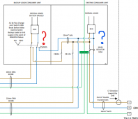
I have a Solis RHI hybrid inverter and I'm using this diagram to wire it.

I will be wiring it very similar to this diagram but I'm having trouble wrapping my head around the consumer unit section.

Where I've circled in blue here, would that part be a henley block?

and then where I've circled in red, would that be a switch like this one? (this one is 63a)

Finally, I struggle to see how the critical loads will have power on a normal day to day basis when the switch is set to inverter, because the AC OUTPUT that connects the critical loads only comes into play when EPS is activated?
Thanks for your help!
I have a Solis RHI hybrid inverter and I'm using this diagram to wire it.
I will be wiring it very similar to this diagram but I'm having trouble wrapping my head around the consumer unit section.
Where I've circled in blue here, would that part be a henley block?
and then where I've circled in red, would that be a switch like this one? (this one is 63a)
Finally, I struggle to see how the critical loads will have power on a normal day to day basis when the switch is set to inverter, because the AC OUTPUT that connects the critical loads only comes into play when EPS is activated?
Thanks for your help!