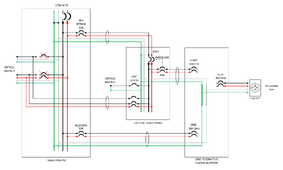
I'm hoping someone can help save me the embarrassment of a failed inspection (or worse). I just can't figure out a neutral arrangement that makes sense for this setup. I'd like to use a 100A subpanel with interlock kit to act as an inverter bypass for the critical loads. However this seems to be complicating the neutral wiring.
NEC 300.3(B) from the top of my head, requires ungrounded conductors (neutrals) to occupy the same conduit or raceway as the ungrounded conductors. This seems to conflict with how I see critical load panels sometimes wired - just bringing over the hots from the main panel.
Additionally there's an issue with parallel neutral paths in numerous places.
Lastly if the SolArk 12k does an automatic N-G bond under grid-down, that means a double bond with the main panel via the critical load bypass feeder, resulting in objectionable currents.
Is there any way to make the below NEC compliant and functionally correct? I was hoping to avoid the cost of a 3pole 50-60A transfer switch (in place of the 100A panel interlock kit), but I think that would solve some problems.
This is a limited-to-home setup; no intention for supplier agreement/sell-back. Not shown below are CTs and conduit ground bonding.
Thanks for any thoughts folks.


