


On_The_Road
New Member
- Joined
- Mar 27, 2020
- Messages
- 104
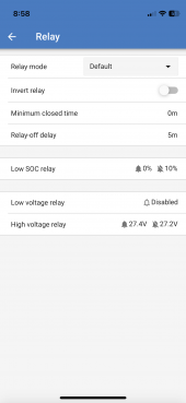
I wanted to trigger my balancers to work via a programable relay on my Victron battery monitor.
I know if you desolder the "Run" bridge on the Heltec you can put a switch there. It seem like the relay of the BMV can supply a NO or NC signal which is 12V. Will that work with the Heltec? Would I have to use the 12V signal from the battery monitor to trigger another relay?
My plan was to have the balancers come on when the battery exceeds 13.5 and turn off at 13.4.
Last edited:
")