diy solar

diy solar

Hot swappable batteries / ideal diodes

jakew009

New Member
Joined
Jun 27, 2021
Messages
25
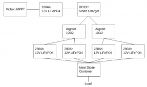
Imagine a system whereby you have 4 x 12v LiFePO4 banks each with their own JBD BMS with common charge / discharge ports.

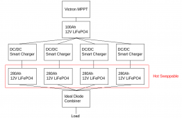
Each of these batteries needs to be hot swappable individually. As in at any point one of the batteries could be taken out of the pack and recharged from the mains before being reconnected to the base station.

The kicker is that when the 4 hot swap batteries are installed into the base station they also need to be connected to a solar array to recharge them.

Th system is used for powering a 50W load.

How would you approach this?

At the moment I have two thoughts:

a) connect the solar array to a dedicated battery that is never removed. Use 4x DC-DC chargers to charge the hot swappable batteries from the solar battery.
Then use 4 more dc/dc converters to connect the hot swap batteries to the load.

Advantage is that everything is isolated. Disadvantage is that we have wastage from all the DC converters.

b) connect the MPPT directly to the batteries using ideal diodes. Connect the load using ideal diodes.

In this situation the load side would work fine because the highest voltage battery would do all the work until it started to equalise with all the others.

But the bit I am not sure about is the solar charge side. It will be a Victron MPPT if it makes any difference.

Will the solar charge controller get confused? The current will initially flow into the battery with lowest state of charge, until it’s voltage starts to match the others when they will start charging as well.

My concern is the solar charge controller might hold the voltage at 14+ volts whilst the lowest battery is still charging, whilst the other batteries could already be at 100% charge.

Option c) is possibly using DC/DC chargers on the charge side, and ideal diodes on the outputs.

Ideas?
 
Why not just pull wire and keep it all connected? How far are these batteries getting transported for charging?
 
Why not just pull wire and keep it all connected? How far are these batteries getting transported for charging?

These things will be deployed at the side of the highway for around 18 months. A little van will come along occasionally and swap the battery packs if the solar is not able to keep up.

The people doing the battery swapping need it to be idiot proof.. I can't guarantee they won't end up connecting a 100% battery with a 5% battery. Hence why I can't simply parallel them up.

We will have software running on the units so we will be able to make sure we discharge the lowest SOC battery first / charge the highest one first.
 
This is probably the simplest way of doing it.
I can toggle the individual chargers on/off and it means I won't lose comms with the unit if some numpty disconnects all 4 hot swappable batteries at the same time.

Screenshot from 2022-08-06 23-20-43.png
 
If all batteries are connected to the buss bar in the star configuration then you can use non-polarized circuit breaker on each battery, just like what they used in the rack mount batteries then you can turn off the battery that you want to remove from the system to be serviced.
 
If all batteries are connected to the buss bar in the star configuration then you can use non-polarized circuit breaker on each battery, just like what they used in the rack mount batteries then you can turn off the battery that you want to remove from the system to be serviced.

How does that help in the scenario where the technician has four 5% SOC batteries, and he only swaps two of them for 100% SOC ones?
There will be massive current flow from the 100% batteries to the 5% ones, tripping the breaker.
 
In your post #3 you do have at least two batteries in parallel so unless you remove both at the same time.
What is the purpose of the ideal diode combiner, on the positive side where they are joined together, I guess, to the load?
 
In your post #3 you do have at least two batteries in parallel so unless you remove both at the same time.
What is the purpose of the ideal diode combiner, on the positive side where they are joined together, I guess, to the load?
The Argofet is basically an ideal diode. So it will allow current to flow from it's input to either of it's output, but it is not possible for current to flow into the outputs. Therefore the batteries would never be connected.

The ideal diodes on the output side are to allow any of the 4 hot swappable batteries to power the load, without allowing any current to flow between the hot swappable batteries (which might be at wildly different states of charge).
 
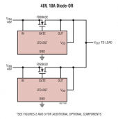
That schematic can't be right, it is using N channel MOSFET FDB3632 which has body diode, the Anode of the body diode is on the Source pin which is connected to the B+ VinX, the Cathode is connected to the Drain pin which is connected to the load, so even if the MOSFET is OFF, the current will still flow from Source to Drain to the load due to the body diode of the MOSFET.
Why would they connect B+ to the Source pin of the N Channel MOSFET? I wonder if the Application Engr. actually tested the circuit. It is bad when the Schematic library does not show the body diode of the MOSFET, I always do that when I create library for my Altium.

 
Last edited:
Does each station need four batteries? Each battery should give 50 hours run time plus solar.

How sensitive is the equipment if a voltage based relay simply switches over if the single battery gets low? Only switching 5 amps. Could be wired to sequence 4 batteries in which case a weekly check would be sufficient to replace any or all low batteries.

This would have the advantage of depleting the batteries in sequence so that just the empties need replaced. If they all deplete together they could all be at 40% and need all four replaced vs just replace 2 or 3 that are empty.

A volt meter on each battery would indicate to replace.... hopefully one at a time.

Solar would be connected to the load and feed the battery being used.

Otherwise the Ideal Diode combiner looks fine. Not sure about the Solar-Battery-DC charger set up. Seems like the chargers would just deplete the small battery.
 
How many solar panels are you using?

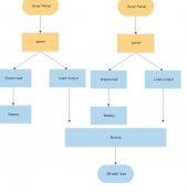
I have a small victron mppt 75/10 smart solar, it doesn't seem to freak out if I connect or remove a battery on it, even while it's running during the day with a small solar panel on it. It also has load outputs that can be set to only output based on your choice of voltages from the battery. It also keeps running for connectivity so long as it has a solar panel on it, even without a battery.

You could possibly just run multiple small victron mppts, let them each charge a battery of their own, and divert to a combined load bus bar using their load output instead of directly hooking your load to the batteries. Their load outputs are big enough to individually support a 50watt load.

For safety, you would just need some disconnects of some type to cut the battery from each mppt for replacement.
 
Last edited:
Does each station need four batteries? Each battery should give 50 hours run time plus solar.

How sensitive is the equipment if a voltage based relay simply switches over if the single battery gets low? Only switching 5 amps. Could be wired to sequence 4 batteries in which case a weekly check would be sufficient to replace any or all low batteries.

This would have the advantage of depleting the batteries in sequence so that just the empties need replaced. If they all deplete together they could all be at 40% and need all four replaced vs just replace 2 or 3 that are empty.

A volt meter on each battery would indicate to replace.... hopefully one at a time.

Solar would be connected to the load and feed the battery being used.

Otherwise the Ideal Diode combiner looks fine. Not sure about the Solar-Battery-DC charger set up. Seems like the chargers would just deplete the small battery.
It is not if you look at the schematic of that so called ideal diode and my explanation my post #11.
 
That schematic can't be right, it is using N channel MOSFET FDB3632 which has body diode, the Anode of the body diode is on the Source pin which is connected to the B+ VinX, the Cathode is connected to the Drain pin which is connected to the load, so even if the MOSFET is OFF, the current will still flow from Source to Drain to the load due to the body diode of the MOSFET.
Why would they connect B+ to the Source pin of the N Channel MOSFET? I wonder if the Application Engr. actually tested the circuit. It is bad when the Schematic library does not show the body diode of the MOSFET, I always do that when I create library for my Altium.

I don’t follow.

I just copied the first diagram I found for LTC4357 (which is the ideal diode chip we use).

The idea of this circuit is that there are two separate power supplies VINA and VINB supplying a single load.
VINA should never be able to backfeed VINB and vice versa. And load should never be able to backfeed VINA or VINB.

Whichever one is higher voltage will supply the load.

The body diode is an irrelevance. The ideal diode chip will turn the mosfet on shunting the diode (and making it ‘ideal’).
No current can flow in the opposite direction.

If you don’t wire the ideal diode chip up properly, it still functions as a diode, just one with a normal voltage drop (from the body diode). Been there before myself…
 
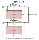
Draw in the body diode into that schematic, even the MOSFET is off, the current from VinX will flow through the body diode to the Load even if the MOSFET is not ON. You do know that you do not connect + Voltage to Source pin of the N Channel MOSFET, correct?
1659830740145.png
 
Last edited:
Draw in the body diode into that schematic, even the MOSFET is off, the current from VinX will flow through the body diode to the Load even if the MOSFET is not ON, you do know that you do not connect + Voltage to Source pin of the N Channel MOSFET, correct?

But that doesn’t matter. It’s meant to be a diode.
In your scenario its still behaving like a diode, just not an “ideal” one.
 
Does each station need four batteries? Each battery should give 50 hours run time plus solar.

How sensitive is the equipment if a voltage based relay simply switches over if the single battery gets low? Only switching 5 amps. Could be wired to sequence 4 batteries in which case a weekly check would be sufficient to replace any or all low batteries.

This would have the advantage of depleting the batteries in sequence so that just the empties need replaced. If they all deplete together they could all be at 40% and need all four replaced vs just replace 2 or 3 that are empty.

A volt meter on each battery would indicate to replace.... hopefully one at a time.

Solar would be connected to the load and feed the battery being used.

Otherwise the Ideal Diode combiner looks fine. Not sure about the Solar-Battery-DC charger set up. Seems like the chargers would just deplete the small battery.

The 4 batteries are needed because a single battery that’s big enough would become too heavy to lift.

We are replacing methanol generators (Google “Efoy generator”) and a single can of methanol has about 7-11kW of energy in it depending on the age of the fuel cell.

But your idea / question is a good one. Why not just cycle through turn batteries in turn.

We would have to handle the momentary loss of power somehow since the equipment is critical.

Re the chargers depleting the small battery - they have a low voltage cut off on them, but we will be able to control them from within the software so we can chose which battery to charge up / how many chargers to switch on at a time (depending on how much sun there is).
 
How many solar panels are you using?

I have a small victron mppt 75/10 smart solar, it doesn't seem to freak out if I connect or remove a battery on it, even while it's running during the day with a small solar panel on it. It also has load outputs that can be set to only output based on your choice of voltages from the battery. It also keeps running for connectivity so long as it has a solar panel on it, even without a battery.

You could possibly just run multiple small victron mppts, let them each charge a battery of their own, and divert to a combined load bus bar using their load output instead of directly hooking your load to the batteries. Their load outputs are big enough to individually support a 50watt load.

For safety, you would just need some disconnects of some type to cut the battery from each mppt for replacement.

This is a really good thought too. Thanks

There will be 3 x 215W panels (out of my control, max size we can get approved from a wind loading / highway visibility / all sort of other crap point of view).

I did originally think about simply having 3 chargers each charging a single battery battery packs. But it’s a bit wasteful if 2 of the packs are 100% and 1 is 10%.

We are going to be up against it in UK winter so I don’t really want to waste any power (hence why I don’t like the wastage from my current idea with the dc/dc chargers).

What I’d really like to know is how a Victron MPPT behaves if connected to batteries at wildly different states of charge via ideal diodes. And what impact it might have on the LiFePO4 cells themselves.

Anyone?
 
Capture.JPG

God, I suck at making charts. Anyhow, repeat for however many batteries and panels you have. Nice thing about having separate MPPTS is each panel gets it's own special loving and redundancy.. and it eliminates all those dc to dc chargers and diodes you were using. Maybe use a few smaller panels, so each Victron can have it's own.. one panel per mppt/battery. The small Victrons are cheap as dirt for their build quality. Other than voltage losses from running smaller strings (which would be very minimal), you don't lose much on multiple conversions this way.

This also keeps you from having any single point of failure.. other than the busbar. And the only thing touched by your "technicians" is the disconnect and the connections to the one single battery behind it.
 
Back
Top