diy solar

diy solar

Hot swappable batteries / ideal diodes

View attachment 105672

God, I suck at making charts. Anyhow, repeat for however many batteries and panels you have. Nice thing about having separate MPPTS is each panel gets it's own special loving and redundancy.. and it eliminates all those dc to dc chargers and diodes you were using. Maybe use a few smaller panels, so each Victron can have it's own.. one panel per mppt/battery. The small Victrons are cheap as dirt for their build quality. Other than voltage losses from running smaller strings (which would be very minimal), you don't lose much on multiple conversions this way.

This also keeps you from having any single point of failure.. other than the busbar. And the only thing touched by your "technicians" is the disconnect and the connections to the one single battery behind it.

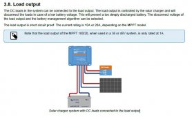
How are you preventing a 100% battery feeding a load of current to a 5% battery?

Or does the Victron Load output already function as an ideal diode and prevent back feeding?
 
How are you preventing a 100% battery feeding a load of current to a 5% battery?

Or does the Victron Load output already function as an ideal diode and prevent back feeding?

I think it's an isolated one way style output, it doesn't send anything back to the battery, just pulls from it. It's like a little separate dc to dc charger built into the mppt.

I could certainly be mistaken though.. in which case my solution sucks. :)

Capture.JPG
 
Last edited:
I think it's an isolated one way style output, it doesn't send anything back to the battery, just pulls from it. It's like a little separate dc to dc charger built into the mppt.

I could certainly be mistaken though.. in which case my solution sucks. :)

Seems the Load output will indeed back feed the battery: https://community.victronenergy.com...tsolar-is-charging-from-load-output-when.html

I’d you think about it it makes sense - they must just be using a P channel mosfet to switch the load output, and the body diode would allow reverse current.

I’d hazard a guess the Victron would release the magic smoke in the hypothetical scenario of low SOC battery connected to high SOC battery ?

But it could easily be solved with ideal diodes in line with the Victron load outputs.
Which would benefit you from not having a single point of failure.. like the 100ah 12v batter and single mppt in the earlier proposals.
 
I figured since they were limiting the outflow to 15-20amps, and only 1amp on the 48v model/setting that they had some way of controlling it and were only pushing current. I guess my ignorance is showing.. :cry:

On the plus side, I am now aware of the limitation and won't plan my system(s) around the feature without ideal diodes. You would need a pretty big ideal diode for a 100ah+ battery, I would imagine.
 
We will have software running on the units so we will be able to make sure we discharge the lowest SOC battery first / charge the highest one first.
I am still intrigued by the sequential relays. If the software can sense voltages separately and give a signal it would seem the sequential relays could be controlled by the software. At the same time the solar could be directed to a low battery though a controlled DC-DC converter.

To avoid the break in power when switching there could be a similar battery connected to the end of the string with the Diode combiner.

Send a signal daily on the battery status.

I like the idea that a battery or multiple batteries are fully depleted when the person is sent out swap.

If it is easier the batteries could be set up in pairs and then replaced as pairs. They would have voltages matched when charging.

So I think your idea is basically

4 batteries
1 solar charge controller
A relay between the solar charge controller and each battery.

We would program it so only one relay was switched on at a time, in effect connect the solar charge controller direct to the battery.

The only downside of this is that the solar charge controller would momentarily shut down when we switched between battery banks.

Hmmmm

We would some fairly chunky relays / mosfets

Edit: theoretically we could actually just use the mosfets on the BMS itself..
 
Hmm not sure that disconnecting the battery under load with the solar still connected is wise

It’s also going to be quite inefficient charging just one battery at a time once the charge rate starts slowing down.

If the panel is generating 50 odd amps, but the battery is only accepting 20, we are wasting 30. With 4 individual dc/dc chargers, each battery could be pulling an average of 12.5 amps maxing out the solar.

Obviously we could start connecting multiple batteries in parallel with the relays once the voltages are similar, but it all gets a bit complicated…
 
Another idea would be to scrap the idea of recharging the hotswappable batteries and simply have a larger permanently connected battery that will do the summer via solar, then plug in a hot swappable battery when we need to give the system a boost.
 
Back to the ideal diode. I typed the FET into the search engine and it pointed me to a series of Infineon P FET. And nobody uses P FETs for anything because they are weak. I had never looked up the LTC4357 but assumed it had a charge pump which could supply the positive gate voltage and it does. The rules of physics has not been violated.
 
Can a methanol generator be dropped off to recharge the pack overnight as needed? Could get some additional life from them.
 
Can a methanol generator be dropped off to recharge the pack overnight as needed? Could get some additional life from them.

We’re trying to get rid of the fuel cells. The cost per kWh is somewhere around $30!
 
Stupid question : why not parallel everything ?

Top balance the 4 batteries initially, wire them in parallel, put the 3 mppt in parallel too (victron mppt can also communicate and sync with data cables). The batteries should not get out of sync.

If you need to fill up the batteries, just plug a full battery through a DC-DC charger which will limit the charging current to what you want.
 
Back
Top