Hedges
I See Electromagnetic Fields!
- Joined
- Mar 28, 2020
- Messages
- 21,809
My car starting battery is probably 30Ah, and 700 CCA. Two of them in parallel for a diesel pickup.
I had a 100Ah AGM bank for PV, now 400 Ah AGM.
There's a table down in this link:
 www.blueboxbatteries.co.uk
100 Ah AGM, 4100 amp short circuit current. So my 400 Ah might be 16000 amp short circuit.
The Square D QO has a DC interrupt rating good enough for the 100 Ah bank, but it isn't enough for the 400 Ah one.
10 to 30A breakers have 4000A interrupting, barely enough for the 100 Ah. 35 to 70A have 10000A interrupt rating.
These breakers would be OK for PV disconnect if Voc low enough.
Class T - yes, that is what I use. 20,000A interrupt rating.
I guess anything larger than 400 Ah or 500 Ah AGM would be too big.
Lithium possibly even smaller.
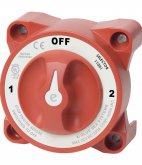
 www.bluesea.com
I had a 100Ah AGM bank for PV, now 400 Ah AGM.
There's a table down in this link:
Battery Internal Resistance & Short Circuit Current.
A study of battery internal resistance and short circuit current discussing how manufacturers calculate these values.
www.blueboxbatteries.co.uk
100 Ah AGM, 4100 amp short circuit current. So my 400 Ah might be 16000 amp short circuit.
The Square D QO has a DC interrupt rating good enough for the 100 Ah bank, but it isn't enough for the 400 Ah one.
10 to 30A breakers have 4000A interrupting, barely enough for the 100 Ah. 35 to 70A have 10000A interrupt rating.
These breakers would be OK for PV disconnect if Voc low enough.
Class T - yes, that is what I use. 20,000A interrupt rating.
I guess anything larger than 400 Ah or 500 Ah AGM would be too big.
Lithium possibly even smaller.
Class T Fuse - 350 Amp - Blue Sea Systems
Use with Class T Fuse Blocks for circuit protection of devices including inverters. high interrupt capacity for large battery banks including Lithium-ion and TPPL batteries.
www.bluesea.com