diy solar

diy solar

How to wire a DC breaker?

pda1

New Member
Joined
Feb 16, 2021
Messages
309
Nothing's easy!

Here's the breaker I'm trying to wire up; CHTAIXI Breaker

Problem is.....I can't figure out which side in the Source (power side) and Load side (device DC is being sent to)

'You have any idea?
 
That's a tough one...
One more thing to note/check: Use a DMM with continuity test to make sure the positive pole is really under the top positive, and Sam for the negative. I have seem videos on YT that say that some of these are cross, and can cause fire if connected the wrong way.
 
Nothing's easy!

Here's the breaker I'm trying to wire up; CHTAIXI Breaker

Problem is.....I can't figure out which side in the Source (power side) and Load side (device DC is being sent to)

'You have any idea?
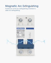
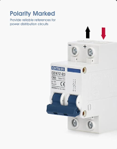
One of the pictures in the Amazon description seem to make it pretty clear to me. Top right of the breaker has the Pos. connection coming into the breaker. The terminal exactly below that would the Pos going out to the load. The other terminal at the bottom would be the return wire from the load (Neg lead), and the top terminal on the left would be the Neg lead going back to the source.
 
One of the pictures in the Amazon description seem to make it pretty clear to me. Top right of the breaker has the Pos. connection coming into the breaker. The terminal exactly below that would the Pos going out to the load. The other terminal at the bottom would be the return wire from the load (Neg lead), and the top terminal on the left would be the Neg lead going back to the source.
I hope that's right.

Anyone disagree with that determination?
 
  • Like
Reactions: Zil
I hope that's right.

Anyone disagree with that determination?
Did you look at all the pics for that breaker. There are arrows showing direction of current flow along with colors indication polarity....Red coming into the breaker and Black returning to the source voltage
 
pda1 is correct.
However I never use a breaker in that application. Fuses are never wrong about direction.
 
Did you look at all the pics for that breaker. There are arrows showing direction of current flow along with colors indication polarity....Red coming into the breaker and Black returning to the source voltage
Yes, I did. Say, take a look at this picture. Notice on the + side of the breaker there's a small diagram. That's where I see the diode.

1640460537620.png
 
pda1 is correct.
However I never use a breaker in that application. Fuses are never wrong about direction.
The breaker is used to quickly open the circuit between the MPPT and the battery/Load side. I want everything down range of the MPPT to be de-energized (except the batteries, of course).
 
Yes, I did. Say, take a look at this picture. Notice on the + side of the breaker there's a small diagram. That's where I see the diode.

View attachment 77120
DC breakers like this one, many times have "magnetic blow out coils" inside them. With Direct current, there is not a voltage zero crossing point like there is in Alternating Current. Because of that, when a DC circuit is opened or interrupted, the arc is much harder to extinguish, so the magnetic blow out coils force the arc to extinguish quicker than if they weren't there. Polarity matters in order to make the blow out coils work properly.
 
See my post #3 for the answer!
You might be right....but I'm need to be sure.

You said, "One of the pictures in the Amazon description seem to make it pretty clear to me.

Don't want to send everything up in smoke and want to be 100% correct.

I "asked a question" on the Amazon listing and if there's a reply then that'll provide the answer.

Geez, why can't the supplier/manufacturer makes this stuff easy?!
If it makes you feel any better, I've been a Journeyman Maint Electrician since 1980. Thirty years of that work history was in a large Steel Mill with hundreds of overhead cranes. Two things about those cranes.....probably 95% of them ran on 250VDC. We had six overhead cranes that had a lifting capacity of 400 Tons or 800,000 lbs. I've worked on DC equipment for the better part of my life, so just a bit of experience there. Every single one of the the huge DC contactors for DC motor control of the cranes had arc suppression via a blow out coil and an arc chute to help direct the arc away from the contact tips.....one of which was a stationary contact and the other a moveable contact. Obviously those were/are much larger than the tiny coils inside the breaker that you are looking at, but the same electrical theory applies to both.....just that one of them is on a much larger scale and the other one.......tiny stuff.

So, in closing, as long as you hook it up as I stated in the above post....AND the breaker is sized properly for the load (should be approx. 125% of the expected amperage), you will not have any issues.
 
My thoughts are that as long as you stick to the +ve and -ve markings on the breaker it does not matter which side ( top or bottom ) is source or load because sometimes the current flow direction changes depending on the application i.e. if the breaker is between the battery and the inverter. Sometimes the battery powers the inverter and other times the inverter charges the battery. Comments welcome.
 
Similar style breaker shown with wiring (except this brand PUFA, has the + and - opposite as the CHTAIXI breaker)...

1640468204642.png

The above wiring indicates bottom of breaker will connect to the load (in this case being a charge controller)... Although, I'd almost wonder if Pierre is onto something, that it doesn't really matter which side is supply vs load, as long as the + and - read right polarity...


CHTAIXI breaker showing - on left and + on right:
1640468424903.png

I'd just wire the supply coming in on top, observing - and + according to labeled, and run the load off the bottom, and call it a day, go eat some turkey dinner after...
 
This was on here some time back. The conscious was the markings are on the most pos and most neg. So not really designed to be used in bidirectional like protection of battery. But for panels they would be connected to the end with the marking.
 
Conventional wisdom in the Electrical field is that supply voltage always comes in at the top of a breaker/service disconnect/switch, the load is connected to the bottom terminals. One of the main reasons is safety. I'm sure most have you have seen a service disconnect....even a small one like the ones that might be on an Air Conditioner outdoor unit. When you pull the switch handle down to disconnect it, many/most of the time you can see the blades that go into the stabs at the top of the switch. If the line side of the power came into the bottom of that switch, when you opened the switch/disconnect, the blades would be exposed and someone could accidentally touch the blades and get electrocuted. The top part of the switch that the blades go into, are usually protected with some sort of arc chute or insulated material and keep you fingers, hands, etc away from the live voltage. This has been a practice for as long as I can remember, and I started my apprenticeship in early 1977. I'm sure it proceeded me, so suffice to say, that practice has been around for quite a while.
 
This was on here some time back. The conscious was the markings are on the most pos and most neg. So not really designed to be used in bidirectional like protection of battery. But for panels they would be connected to the end with the marking.
Do you mean "consensus"? In further reading you might be correct. I discovered that the side of the breaker that has MORE power to it should be connected to a specific side of the breaker. The side of the breaker that'll be presented with LESS power should be connected to the remaining side.

That said, the battery side would be the MORE power side...I guess.

Now, exactly what that means in my situation I have no idea.

P.S. As said before I posted a question on Amazon about wiring of this breaker. 'Got a reply which I had zero confidence in, i.e. "wire however you'd like".
If you are hoping to find intelligent, knowledgeable, and accurate responses on the question section of Amazon replies, your odds are way less than 50%....if even that high. This forum is filled with people who have in many cases, years and years of experience with electrical equipment, engineering degrees in some instances, and a desire to help those who truly want/need help. I know where I'd place my bet. ?
 
Battery charges and discharges, 2 way current flow not a good place for this breaker. The breaker is only designed to extinguish arc internally in one direction. The markings indicate the input power end. If you connect in reverse it will trip but my continue to feed power while arcing across a air gap internally and burn the breaker up.
 
Back
Top