diy solar

diy solar

How to wire a second 4S BMS to my 12V system in parallel

Yeah like I said in the first couple threads, you could always buy two BMSs like the JK 4s 200a you mentioned, and then split your 2p4s, into two separate batteries, it would give the same amps you have now, just splitting the amps across two batteries/BMSs.. so it would be 1p4s per battery, which would then be 4s2p as a double battery pack.

Mine look like this, where the back side of these packs is a mirror image of this side (this aluminum clamp is two 4s batteries with BMS on this side, and BMS on the other side)...

View attachment 173366
OMG, that is awesome. Very professional build.
Then I would have to 1 gage wire and connect the positives of each group together and connect the two C- together.
Right?
 
OMG, that is awesome. Very professional build.
Then I would have to 1 gage wire and connect the positives of each group together and connect the two C- together.
Right?

Yeah, exactly that, think of it as two completely separate batteries, just bridged together (outside of each BMS), on C- and +

You split the difference, perfect for two 200a BMSs, that are smaller than the single 500a, but same power to the endpoint.

Also makes troubleshooting easier, because I can turn off one battery, take it out, fix it or whatever, without disturbing the other production batteries, so better fault tolerance as well.
 
Your Overkill smart bms looks easy to wire compared to the JK. I still have no real idea how to wire the JK smart bms for a 4S battery,
 
Last edited:
Your Overkill smart bms looks easy to wire compared to the JK. I still have no real idea how to wire the JK smart bms for a 4S battery,
(sorry for the absence, had a dinner party!)
I think all the 4S BMSs wire up exactly the same way. That a shouldn't sway your thinking.

Its disturbing the Daly will not accept configurations. I only have dumb Daly BMSs so don't even have a Daly app.

If i were you I'd continue with your existing setup that is working just fine. I'd keep looking for a solution to setting up
 
@MisterSandals
Thank you for trying.
I had a friend who trashed his smart daly with one of those 5a smart balancers you can buy for $17. He did buy a JBD 200 amp and is happy with that one.
 
I was looking at the same picture, yes I googled it and it took awhile but I finally found a 4S picture.
Yes it needs a power supply and I was hoping the red 4 wire led would already be attached to the power led.
I just checked my batteries before bed and I have three showing 3.42 and the others 3.32 to 3.35.
Thank you for helping, if you have any more ideas, I'll be back tomorrow morning.

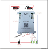
The only power supply the BMS needs is the first balance lead (on right, the black one, going to the absolute ground of the 4s pack), and the last lead (on left, the red one on the other end of the balance lead connector, going to the absolute positive of the 4s pack). They usually number this terminal block connector from right pin counting up toward the left.

The 'controller' you see at top of diagram indicates your load (inverter), and to the right of that is the 'charger' (MPPT charge controller, or other suitable charger source). Those are just examples. There is no external power supply needed, the BMS gets it's power to operate right off the 12v battery itself (through that balance lead connector harness).
 
Last edited:
The only power supply the BMS needs is the first balance lead (on right, the black one, going to the absolute ground of the 4s pack), and the last lead (on left, the red one on the other end of the balance lead connector, going to the absolute positive of the 4s pack). They usually number this terminal block connector from right pin counting up toward the left.

The 'controller' you see at top of diagram indicates your load (inverter), and to the right of that is the 'charger' (MPPT charge controller, or other suitable charger source). Those are just examples. There is no external power supply needed, the BMS gets it's power to operate right off the 12v battery itself (through that balance lead connector harness).
Yes, I see that in your diagram. My Victron MPPT solar charge controller needs the negative wire attached to the C-. WoW I've had mine attached incorrectly for years. :oops: I wonder if changing that connection would make a difference with my cells? Of course right now for the past two weeks
I've been house setting for family and RV has been on shore power and the solar charge controller is off.

I do know I need to reattach my large inverter to the C-. Just haven't gotten to that yet.
The JK 200A smart inverter peaks at 350 amps for a minute or two according to their website.
That should handle my 4000 watt inverter.
 
Back
Top