


You are using an out of date browser. It may not display this or other websites correctly.
You should upgrade or use an alternative browser.
You should upgrade or use an alternative browser.
I have a 48v (56v) LiFePO4 battery array that I need a disconnect switch. Does anyone have any recommendations?
- Thread starter ril3y
- Start date
Ampster
Renewable Energy Hobbyist
Perhaps a contactor. They can handle that Amperage and it could be a good way to turn on and off the pack.This is going on my solar powered golf cart as a quick disconnect just for safety. Does anyone have any ideas?
Daddy Tanuki
Solar Wizard
yeah one of those big HD contactors with a input that turns it off an on by gournding or supplying power. a small switch that opens the relay and you are discconected.Perhaps a contactor. They can handle that Amperage and it could be a good way to turn on and off the pack.
yabert
Solar Enthusiast
Gigavac HBD41 can do the job.
Or Littelfuse SR SERIES MASTER DISCONNECT SWITCHES.
Still, a contactor like the Gigavac GV200 (12V or 48V coil voltage) is a good idea.
Don't be fear by your peak amps ''up to 500-600A'', a 200A contactor often can take high amps for seconds/mins.
Or Littelfuse SR SERIES MASTER DISCONNECT SWITCHES.
Still, a contactor like the Gigavac GV200 (12V or 48V coil voltage) is a good idea.
Don't be fear by your peak amps ''up to 500-600A'', a 200A contactor often can take high amps for seconds/mins.
This one is rated at 600A. It’s pricy at about $80 but Marinco is a quality brand.This is a bit tricky as the battery disconnect has to handle up to 500-600A.
Heavy Duty Battery Switch - 600A Continuous
The 720 Heavy-duty Battery Switch fits into the same contour lock system as used on the battery distribution system. Rated at 600A continuous and 2500A cranking. It is well suited to larger vessels. As with the 701, the 720 can be recessed or surface mounted. The 720 uses the same style of self...
www.bepmarine.com
yabert
Solar Enthusiast
What Heavy Duty Battery Switch on earth is not rated for a define voltage???This one is rated at 600A.
600A at 12V is not the same than 600a at 48V.
What Heavy Duty Battery Switch on earth is not rated for a define voltage???
600A at 12V is not the same than 600a at 48V.
Attachments
yabert
Solar Enthusiast
Nice! Thanks GuyG
Thanks, guys! The BEP one looks like exactly what I am after. I already have an SSR (https://www.aliexpress.us/item/3256803495863859.html) that is being controlled by a master controller (a board I designed) that will enable power to the motion controllers. I didn't want to go the route of a contractor just because I didn't want to have to provide a constant current to enable it. Also, while not LIKELY the idea of contact welding does not make a safety switch IMO a great idea. I really just wanted this to be a manual disconnect that will interrupt the main 48v line from the battery to the rest of the system.
Heres a pic of my work so far if anyone cares")

Heres a pic of my work so far if anyone cares
schmism
Solar Addict
So as the existing wire is no were close to handling 600a, the requirement that the disconnect do it seems.... pointless.. I really just wanted this to be a manual disconnect that will interrupt the main 48v line from the battery to the rest of the system.
I have multiple runs of 2ga. I am going overboard on purpose. Also the motor controllers are NOT going through the BMS as they are wired directly to + on the battery (ssr in between)So as the existing wire is no were close to handling 600a, the requirement that the disconnect do it seems.... pointless.
schmism
Solar Addict
Not in the photo you attached you don't?I have multiple runs of 2ga. I am going overboard on purpose. Also the motor controllers are NOT going through the BMS as they are wired directly to + on the battery (ssr in between)
Yeah, it's not hooked up correctly right now. This is why I was asking for a disconnect the 2ga (single right now) is going back to power both of the controllers for testing. However, I am going to be hooking up 2x 2ga (or 0ga) directly from the battery to the switch, and from the switch, it will go back to the SSR.
DIYrich
Solar Wizard
Fuse for the motor controllers?I have multiple runs of 2ga. I am going overboard on purpose. Also the motor controllers are NOT going through the BMS as they are wired directly to + on the battery (ssr in between)
If the motor controllers bypass the "disconnect", then why 600 amps?
No ALL positive 48v will go through the disconnect switch. The controllers have a fuse on them 150A each. The SSR is acting as a "key" that will enable power to the motor controllers. I want the cart to turn on but not power the motor controllers unless the key is "on" (vs acc).Fuse for the motor controllers?
If the motor controllers bypass the "disconnect", then why 600 amps?
The BMS is used to manage charge and power on the rest of the card (android head unit, stereo system amp, lights etc).
The point of having the motor controllers outside of the BMS was to not have to purchase some expensive BMS that would handle all of the current the motors drive. However, when the BMS reaches the low-level state it shuts off the power to the rest of the system. This then shuts down the power to the motor controller SSR thus disconnecting the +48 line to both of the controllers.
I hope that makes more sense. If there is a flaw in the system please point it out!
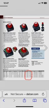
Below is the current for charts for my model (both of them)

Last edited:
Similar threads
- Replies
- 2
- Views
- 512
- Replies
- 8
- Views
- 346
- Replies
- 3
- Views
- 968
- Replies
- 20
- Views
- 1K