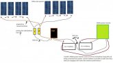
how do i go about connecting a bunch of solar panels together and into the one port on my mttp charge controller im looking at about 8 100wat pannles is their some kinda fuse box/junction box i can use? RICH SOLAR 100 Watt 12 Volt Polycrystalline Solar Panel and a Epever MPPT Solar Charge Controller 12V/24V Solar Regulator 150V 40amp someone on facebook told me i shod have them in parallels of 4 then the 2 sets of 4 in series? pic is what im thinking so far.


You are using an out of date browser. It may not display this or other websites correctly.
You should upgrade or use an alternative browser.
You should upgrade or use an alternative browser.
i need some help figuring out my setup for my rv
- Thread starter justison
- Start date
John Frum
Tell me your problems
- Joined
- Nov 30, 2019
- Messages
- 15,230
I'll leave the pv side to somone else but 10 awg is grossly undersized for the system side.
3000 ac watts * 1.15 conversion factor / 12 volts low cutoff = 287.5 dc amps
287.5 dc amps * 1.25 fuse headroom = 359.375 fuse amps.
That means 3/0 awg or 4/0 awg depending on the length.
10 awg is 6 mm2 of copper.
3/0 awg is 95mm2 of copper.
4/0 awg is 120mm2 of copper.
 baymarinesupply.com
3000 ac watts * 1.15 conversion factor / 12 volts low cutoff = 287.5 dc amps
287.5 dc amps * 1.25 fuse headroom = 359.375 fuse amps.
That means 3/0 awg or 4/0 awg depending on the length.
10 awg is 6 mm2 of copper.
3/0 awg is 95mm2 of copper.
4/0 awg is 120mm2 of copper.
Interactive Wire Size Calculator
Battery Chargers, Inverters, Solar Components, and Wiring Supplies for Boats, RVs, and Off-Grid Applications.
baymarinesupply.com
boondox
Chief Engineer, RedNeckTech Industries
- Joined
- Mar 1, 2020
- Messages
- 789
Firstly, I have no idea of what the max VOC of your panels is and what they add up to in series. Make sure that you charge controller can handle that voltage. Be aware that cold days can increase the voltage, check to make sure you are within spec. On an RV the panels are usually mounted flat so they are less likely to hit peak voltages but it is good design practice to stay within spec.
You should put fuses or breakers on either side of the charge controller. I prefer breakers, make sure they are DC rated. These are for working on the system as much as safety. Look for a "combiner box" to tie your arrays together and mount the input side breakers. Listen to SJ about the wire gauge. You will notice that his calculations take into account a properly sized fuse for the inverter size. The object of that fuse is to protect the wire, not the inverter.
You should put fuses or breakers on either side of the charge controller. I prefer breakers, make sure they are DC rated. These are for working on the system as much as safety. Look for a "combiner box" to tie your arrays together and mount the input side breakers. Listen to SJ about the wire gauge. You will notice that his calculations take into account a properly sized fuse for the inverter size. The object of that fuse is to protect the wire, not the inverter.
Your diagram is right, 4 panels in series x 2 then parallel those 2 sets together, this saves you on cables etc.
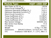
Your VOC is 21.2v on those panels so 2 strings of 4 will be 84.8v
Your ISC is 6.02a on those panels so 12.04a with the two strings in parallel
So your 150v 40amp charge controller is absolutely fine and wiring up in 2 sets of 4 is probably the best option for your 24v battery setup.
You could use combiners instead of a combiner box, I think this is a preference thing.
You would need a couple of these https://tinyurl.com/y4jz6n55 then some normal MC4 leads for connecting up and then to get you inside the RV to your DC breaker.
The cable from your charge controller to the batteries should be fine at 10awg assuming the length isn't crazy but your cable from battery to inverter like mentioned above needs to be pretty large.
Do you know what batteries you have and or getting, that is really important to know you can get enough charge into them and how long they are going to last through the night etc.
On a good day you are probably going to see around 3000wh from your panels so should easily charge a couple of 150ah batteries max probably around 250ah so you need to think about how much power you are going to draw.
Hope it helps.
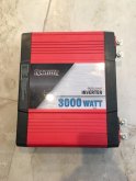
atm my 2 random rv batteries are in 12v and not 24v mainley becuse i dont know what the traveler 3000 watt inverter is doing
it has 2 sets of power cables coming out the back of it so im gessing its useing 2 12v to make 24v inside its self wold it be better for the soaler side of things to have battery's in 24v?? i plan to get a pair of big good batteries at some point. also i was wondering if any one is familiar with my charge controller (Epever MPPT Solar Charge Controller 12V/24V Solar Regulator 150V 40amp) is it just plug and play or do i have to play with the settings? can i just pop 24v battery setup into it without hurting it?
it has 2 sets of power cables coming out the back of it so im gessing its useing 2 12v to make 24v inside its self wold it be better for the soaler side of things to have battery's in 24v?? i plan to get a pair of big good batteries at some point. also i was wondering if any one is familiar with my charge controller (Epever MPPT Solar Charge Controller 12V/24V Solar Regulator 150V 40amp) is it just plug and play or do i have to play with the settings? can i just pop 24v battery setup into it without hurting it?
Attachments
The peak voltage any PV panel generates is achieved really quite early on in the morning and stays pretty stable into the evening, only the current really changes with differing solar irradiance levels. You don't often see this because the MPPT controller artificially modifies the PV voltage when trying to identify and track the maximum power point.On an RV the panels are usually mounted flat so they are less likely to hit peak voltages
They look in parallel to me... ??Oh I see the batteries are in series.
Do not guess, read your inverter's datasheet.so im gessing its useing 2 12v to make 24v inside its self
A solar charge controller [that supports multiple battery system voltages] doesn't care whether you connect a 12V (nominal) or 24V (nominal) battery system to it, but your system design as a whole does. For example, your charge controller has a maximum 40A charging current which means that it can only deliver 584W into a 12V (nominal) battery. If you connect more than 584W of PV, it will just clip the input (up to the maximum PV power specification) so some of your 800W array will be 'left on the table'. With a 24V(nominal) battery it can deliver 1,168W. Additionally a 24V battery system would require thinner, cheaper cable. BUT! With a 24V battery system you would need to add a 24V-12V converter to your system to power any 12V loads you may have. My rule of thumb is:wold it be better for the soaler side of things to have battery's in 24v??
1W - 3,000W: 12V battery system
3,000W - 5,000W: 24V battery system
>5,000W: 48V battery system
Your 3,000W inverter is right on the boundary. I would be asking myself, do I really need 3,000W of inverted power? The bigger the inverter, the more losses will be incurred, and the grater will be the quiescent (no load) draw constantly draining my battery.
Other considerations:
- Keep the higher voltage cable runs longer i.e. array-to-SCC: long, SCC-to-battery: short.
- Every circuit leaving your battery should be fused
- Consider adding isolator switches to all sources of power
- Use busbars instead of direct cable-to-device connections
- Consider adding 'split-charge-relay' system to charge your battery (if staying at 12V) from your alternator. DC-DC charger if 24V or you switch to lithium-ion.
NCblueridge
New Member
- Joined
- Jul 31, 2020
- Messages
- 154
The peak voltage any PV panel generates is achieved really quite early on in the morning and stays pretty stable into the evening, only the current really changes with differing solar irradiance levels. You don't often see this because the MPPT controller artificially modifies the PV voltage when trying to identify and track the maximum power point.
They look in parallel to me... ??
Do not guess, read your inverter's datasheet.
A solar charge controller [that supports multiple battery system voltages] doesn't care whether you connect a 12V (nominal) or 24V (nominal) battery system to it, but your system design as a whole does. For example, your charge controller has a maximum 40A charging current which means that it can only deliver 584W into a 12V (nominal) battery. If you connect more than 584W of PV, it will just clip the input (up to the maximum PV power specification) so some of your 800W array will be 'left on the table'. With a 24V(nominal) battery it can deliver 1,168W. Additionally a 24V battery system would require thinner, cheaper cable. BUT! With a 24V battery system you would need to add a 24V-12V converter to your system to power any 12V loads you may have. My rule of thumb is:
1W - 3,000W: 12V battery system
3,000W - 5,000W: 24V battery system
>5,000W: 48V battery system
Your 3,000W inverter is right on the boundary. I would be asking myself, do I really need 3,000W of inverted power? The bigger the inverter, the more losses will be incurred, and the grater will be the quiescent (no load) draw constantly draining my battery.
Other considerations:
Good luck with you project.
- Keep the higher voltage cable runs longer i.e. array-to-SCC: long, SCC-to-battery: short.
- Every circuit leaving your battery should be fused
- Consider adding isolator switches to all sources of power
- Use busbars instead of direct cable-to-device connections
- Consider adding 'split-charge-relay' system to charge your battery (if staying at 12V) from your alternator. DC-DC charger if 24V or you switch to lithium-ion.
Hi tictag, you posted an interesting thread about how Victron charge controllers deal with excess input from panels. I have a new 100/20 (I know I should have got the 30 but this is a micro build..lol).
Anyway, with my build ( https://diysolarforum.com/threads/my-lightweight-portable-power-station-build.11456/#post-126887) I will have (4) 100 watt panels available, I've added a pic of the specs below.
So the question is, do the same considerations apply with victron controllers when it comes to amps as opposed to volts?
For example, with my (4) panels, I barely exceed the max amp rating (20). Voltage is fine though.
Will it simply restrict the amperage to 20 amps or shutdown because it's a little bit over?
I can hookup them up with a 2P/2S configuration and maybe that is actually a better choice anyway that resolves the amp limitations, but since I am right on the borderline with the amp limitation, I though I would ask.
To connect 2p/2s or would victron ignore the nominal extra amps coming at it?
Others feel free to comment also.
Thanks,
William
Attachments
Last edited:
Don't confuse input Amps with output Amps, in fact it's best to consider the PV-side and battery-side of a MPPT SCC, any MPPT SCC, independently of each other. Victron name their products based on key specs, for the SmartSolar 100|20 that's an input voltage maximum of 100V and an output current maximum of 20A. You could have 1A or 1,000,000A on the input but it would only ever provide 20A on the output (exaggerating to make the point). It's best to therefore think in terms of Watts i.e. Watts in = Watts out (ignoring losses).Will it simply restrict the amperage to 20 amps or shutdown because it's a little bit over?
For example, take any array, any configuration, the 100|20 could only generate a maximum of 292W output into a 12V (nominal) load, or 584W output into a 24 (nominal) load (i.e. max output 20A x 14.6V = 292W, max output 20A x 29.2V = 584W). This is what Victron calls the 'nominal output'.
If you connect more PV input Watts than the nominal output Watts then you are 'leaving power on the table', which is called over-panelling and this if fine, Victron actually recommend over-panelling their SCCs by 30% or so, just be aware that it can never generate more than the nominal output so the input will be clipped, that is, the MPPT will select a sub-optimal maximum power point to reduce power. You can over-panel up to the maximum input specification, which for the SmartSolar 100|20 is 2,000W.
So to answer your question directly, no, it will not shut down, in fact, over-panelling up to around 30% is recommended.
In regards to your array configuration, so long as there are no issues with partial shading, I would connect all panels in series for an array Voc of 85.2 and Isc of 5.83A, this will minimise the losses incurred in your PV cable runs and, therefore, optimise system efficiency and minimise project cost. If partial shading is an issue, then 2S2P would be a reasonable compromise.
Assuming a 400W nominal output:

- The 400W experience little to no input clipping BUT
- Whilst the 520W array (30% over-panelled) experiences more clipping in peak sun, overall generates more power, especially on cloudy/overcast days.
Correction: Power over time is energy, that should read 'energy' in the middle!
Edit: Added further information on over-panelling. Added correction.
Last edited:
NCblueridge
New Member
- Joined
- Jul 31, 2020
- Messages
- 154
Thanks for the great explanation TicTag!, this answers my question and I'm going to wire these panels in series given the panels location.
John Frum
Tell me your problems
- Joined
- Nov 30, 2019
- Messages
- 15,230
They look in parallel to me... ??
I defer to your superior eyesight.
Ironic, I noticed the other week that my close focusing has become deteriorated, I used to be able to see the writing on 0803 SMT components, now I can barely see the board they are soldered to! Just another 'benefit' of progressing years, I guess.I defer to your superior eyesight.
Similar threads
- Replies
- 3
- Views
- 151
- Replies
- 6
- Views
- 362