diy solar

diy solar

If 'PEAK CURRENT 400 Amp' then what size BMS & Cabling?:)

Modular Hippo

New Member
Joined
Apr 13, 2023
Messages
64
Location
UK
Hi Forum,

Yep, beginner hence this thread Category:)

Designing (only on paper so far) a setup where I can drive my boat on solar and use sun/wind to charge my battery bank.

I have my eyes on 2 potential motors (both rated at PEAK CURRENT 400 Amp):

LEM 200 - 95
LMC Marlin - Single Drive System

I am trying to translate the '400 Amp' in to what that means to my choice of BMS and Cabeling to make sure I only have what I potentially need (as costly components).

Forgive my lack of knowledge in the area but are we saying that if you want to drive this motor on 'full speed' you have to provide '400 amp'. In other words, if I had a '200 AMP' BMS and cabling then I could only drive the engine on half max speed (as if go above this I will blow my fuses)?

I have seen examples where user with a similar setup (10 Kwh motor) say 'My BMS' supports '100 Amp' as I do not foresee myself drawing anything above this from the motor'. Someone else mentioned something similar configuration but 200 Amp BMS and cabling... A bit confusing as to what they base this on. Maybe you never drive engine on full and instead use gear ratio to make use of torque to get good RPM against very little Amp input? If so what would that Amp input be?

I guess my question is - What amperage BMS & Cabling would you normally have for a setup like this?:) Fully understand if what I have provided cannot be used to calculate this but thought I make a start. Might get the right questions back to help me figure it out:)

Any feedback that can help me crack this mystery highly appreciated:)

Thanks
Modular Hippo
 
Worth mentioning..... Battery bank is 48 Volt (as this is what the motors require):) Thanks!
 
What exactly are you trying to do with this motor? 20kW is a stout application to be DIYing.
 
When controlling this much amperage you have 2 options.
1) PREFERRED: use a BMS with an output to control an external mechanical contactor with a 600A contact rating.
2) Use at least 3 separate battery banks in parallel each with its own 200A FET based BMS.
 
What exactly are you trying to do with this motor? 20kW is a stout application to be DIYing.
Hi Preppen Wolf,

Thank you for replying:) I believe these motors are 10Kwh and the idea is that is should replace a Yanmar 38HP diesel combustion engine to drive a 36' Aluminum Sailboat. As the engine has a fair amount of torque I have a feeling that you can run motor on lower amperage and use gears to increase RPM. Just need that confirmed somehow, alternatively find someone that has tried this before me:)

Thanks
H
 
I have a feeling that you can run motor on lower amperage and use gears to increase RPM.
The torque curve of many electric motors is fairly constant so the OP may be able to eliminate the need to use gears. If I remember correctly propeller RPMs for a sailboat are usually about 1,000 RPMs since the speed is limited by hull speed.
 
The torque curve of many electric motors is fairly constant so the OP may be able to eliminate the need to use gears. If I remember correctly propeller RPMs for a sailboat are usually about 1,000 RPMs since the speed is limited by hull speed.
Thanks Amster - I struggle with the number of variables to keep in to account: Voltage, Amps, Hull speed, RPM, Propeller Shape/Size, Gears or no gears. When researching there are so much conflicting information, I guess down to a fairly untested area (if you compare to E-Cars etc.). I guess trial and error on a test bench is the way forward. Work out what RPM/Torque I will need to achieve and work backwards:)
 
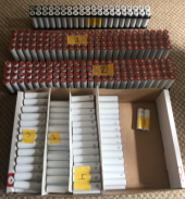
My first step is a battery pack 14S 40+P 48V (540 18650's)
Probably need to learn how to crawl before running as my next step is to figure out best fuse wire to use for the individual 18650. All fun and games, like a pig in shit:) - 430 harnessed so far, another 110 to go. Any ideas around individual 18650 fuses highly welcomed, (I have a spot welder and want to try to stay away from soldering if possible):)

18650s.png
 
Have you thought about contacting the manufacturer for answers? LMC have options for gear reduction on these marine motors and likely can answer your questions about amps in relation to RPMs. I'm sure they can guide you as to what size motor, wiring, contactors, battery banks, etc will work best for your vessel. They likely also know under what circumstances their motor will draw peak current and for how long.
 
Last edited:
The Marlin system has reduction gearing built into the motor assembly and I understand uses a similar motor to the LEM 200, ( this would also need gearing as its torque increases in a linear manner with speed. At hull speed , depending of prop size, will need around 800 to 1200 rpm, a variable pitch prop could be useful.
Typical current will be nothing like 400 amps, my guess is under a 100 amps. Continius safe maximum current would be in the order of 200 amps and by using batteries in parallel, for redundancy and safety can be easily achieved by using 100 amp 48 volt BMS.
I suggest building 2 batteries using Winston LMC prismatic cells, the hard plastic case cells are ideal for marine use and continious current is 3C, thus using 50Ah cells in two 48 volt batteries is practical, with a total cell weight of 50 kg.
Cable, 50mm2 or 70mm2 should be OK.

Just seen you last post, is using those cells a good idea?

Mike
 
My first step is a battery pack 14S 40+P 48V (540 18650's)
Probably need to learn how to crawl before running as my next step is to figure out best fuse wire to use for the individual 18650. All fun and games, like a pig in shit:) - 430 harnessed so far, another 110 to go. Any ideas around individual 18650 fuses highly welcomed, (I have a spot welder and want to try to stay away from soldering if possible):)

View attachment 157735
Oh gosh.
You're in for a lot of work with those cells.
For a battery of the capacity size needed.
Have you considered prismatic cells?
 
Have you thought about contacting the manufacturer for answers? LMC have options for gear reduction on these marine motors and likely can answer your questions about amps in relation to RPMs. I'm sure they can guide you as to what size motor, wiring, contactors, battery banks, etc will work best for your vessel. They likely also know under what circumstances their motor will draw peak current and for how long.
Hi Q-Dog,

Thank you for response.

I have contacted them a couple of times but cannot say the responses were as guiding or in debt as I would have liked. I guess down to every hull being different etc. What they have confirmed is that the engine have a similar output as the engine I am replacing so guess that is a good start.In other words, the choice of motor power seems to be on track (now just need to figure out the rest):)
 
The Marlin system has reduction gearing built into the motor assembly and I understand uses a similar motor to the LEM 200, ( this would also need gearing as its torque increases in a linear manner with speed. At hull speed , depending of prop size, will need around 800 to 1200 rpm, a variable pitch prop could be useful.
Typical current will be nothing like 400 amps, my guess is under a 100 amps. Continius safe maximum current would be in the order of 200 amps and by using batteries in parallel, for redundancy and safety can be easily achieved by using 100 amp 48 volt BMS.
I suggest building 2 batteries using Winston LMC prismatic cells, the hard plastic case cells are ideal for marine use and continious current is 3C, thus using 50Ah cells in two 48 volt batteries is practical, with a total cell weight of 50 kg.
Cable, 50mm2 or 70mm2 should be OK.

Just seen you last post, is using those cells a good idea?

Mike
Hi Mike - Big thank you as your ideas are very close to what I have found myself when doing some research. I will most likely settle for a 200 Amp as anything above I believe is OTT.
As far as battery type goes, Li-Ion is NOT the best way forward but instead Li-Ion phosphate prism cells as you say. What I am currently building is a secondary system that I mainly will act as a bank for lights etc. in the boat BUT with the option to use with the motor if ever needed (in case issues with primary bank). I thought I start playing around/learning the basics using something as basic as the 18650. In all honesty, I also find building the packs extremely therapeutic.:) I will use this 18650 bank as a bit of a test bank as well when I play around with the rest of the components (solar, charge controller, AC/DC converter etc.). The primary bank is intended to be a 10 kWh bank so will cost allot and as there is a big chance that those prism would have to sit around for a while (as I also are in the process of building the actual boat itself) I have decided that this will be my last investment, Hopefully some method in my madness:)
 
Oh gosh.
You're in for a lot of work with those cells.
For a battery of the capacity size needed.
Have you considered prismatic cells?
Hi Timselectric,

Thank you for your response - You are right, not time or cost effective but a whole bag of fun:) and learning loads in the process. If you check my response to Mike you will see master plan. The main battery pack will indeed be based on a Li-Ion Phosphate prism setup but for cost and other reasons they will be my last outlay in this adventure:)
 
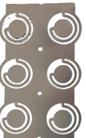
Sorry for side tracking but what do we feel about Nickel Fuses (2P) - Looks like I would save myself a ton of work..... I guess I would have to work out how many layers needed to handle 100amp:

NICKEL FUSE 2P.png
 
Back
Top