diy solar

diy solar

IMO DC Disconnect Rooftop Isolator Switch wiring

OffgridMatty

I know enough to be dangerous!
Joined
Jul 24, 2022
Messages
92
Location
Edwards, NY
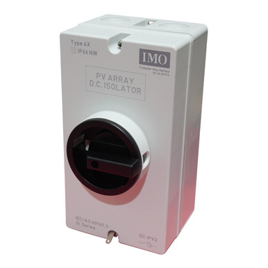
I need some help with the wiring of my IMO DC Disconnect Rooftop Isolator Switch. The paperwork it came with is not clear to me. I think the correct wiring method is to connect the wires in diagonal orientation on each end of the switch. Can someone that has experience with these confirm this. I have a simple single set of PV wires, just one 10AWG red and one 10AWG black. Thanks!

 
I have one of these and yes the wires seem crossed, it is top left to bottom right and vise versa.

I recommend that you check this with a multi-meter to verify yours is the same. Simple just do a continuity test.
 
One more question. Do the wires from the PV panels need to go in the top of the shut off and continue to the charge controller from the bottom? Or does it not matter.
 
I wish I had READ THIS FIRST!
Yesterday we hooked up a new solar array. Someone else did the pre-wiring very neatly with Red for Positive, Black for Negative. The top left was Red in, top right Black in. They assumed that the connections would go straight thru so Bottom left was Red, Bottom right was Black. With no enclosed manual directions. I looked at it and all appeared fine. Because of a time constraint, I made the EG4 6500 PV connections before the last panel went in. We carefully checked + and - on the panels, made the last panel connection and turned the IMO to ON. Nothing happened. I measured the Voc at the EG4 terminals and was shocked to find it measured -1.0 v!! Quickly disconnected and double checked everything. Every one looking very sad! Especially me. We disconnected solar panels and checked continuity thru the IMO. Connections are diagonal, so wiring straight thru will result in reversed polarity! No warnings from Signature and nothing in the 28 page IMO manual.
We reversed connections and turned back on and all was well. We had a group hug and high fives!
I believe this is a high quality HV Disconnect at a reasonable price. Signature should spend a couple cents and enclose a simple wiring diagram.
 
Just wanted to share a little OE...

In the literature there is a picture, along with a description of the engineering features of the switch. When both are studied it can be seen exactly how the voltage is conducted through the switch. This is a rotary knife contact switch, and this is precisely why voltage flows on the diagonal. Regardless as suggested above continuity tests are the gold standard...Image 6-29-23 at 10.12 AM.jpg
 
Back
Top