diy solar

diy solar

importance of earthing a rack battery and its cabinet ??

Hmm, not voltage? DC is safer to a higher voltage than AC.
DC is more dangerous than AC. (No zero point crossing)
What about available current?
current doesn't flow without enough voltage to push it.
Also the threshold for safe voltage level in rapid shutdown was set to 30V (and 240VA in some code iterations). Fixed 48V battery is way way above that.
That is expected to be raised.
Probably in the next code cycle. Due to panels getting larger. But not sure how much. Because RSD is to protect firefighters. And if they're up there, everything is going to also be wet.
 
DC is more dangerous than AC. (No zero point crossing)
I’m pretty sure that the Class 2 circuit limit is 30VAC and 60VDC due to 50/60hz causing more physiological effects

That is expected to be raised.
Probably in the next code cycle. Due to panels getting larger. But not sure how much. Because RSD is to protect firefighters. And if they're up there, everything is going to also be wet.
Raised in voltage or VA? Increasing the limit would make it less safe for firefighters. I don’t think it actually needs to be raised. The RSD devices when in shutdown can hook in current limiters, they anyway need to buck the voltage down to 1V

Raising the limit would be nice in allowing longer series strings, but 30s (current limit due to RSD) is already well above residential limit. Maybe there’s commercial scale installation push for it.

I’m not sure going up from 30VDC would go down nicely with the fire lobby. With wet conditions and a lot of metal axes being thrown around, I don’t think 60VDC limit is smart to use here.
 
Raised in voltage or VA?
DC voltage at the panel. Larger panels are pushing the 60v limit, already.
I think that the Larger panels of the future. Will have to have RSD incorporated into the panels. To isolate the individual panel strings.
 
DC voltage at the panel. Larger panels are pushing the 60v limit, already.
I think that the Larger panels of the future. Will have to have RSD incorporated into the panels. To isolate the individual panel strings.
Limit is 80vdc within the array which is enough for some monster panels. Like over 100 cells which would be a 800W panel with M10 cells.

Actually you can 2s together two 54 cell M10 panels and still be below 80VDC (that’s 75V VOC, so pushing it with temp compensation. Not sure if the temp compensation needs to be accounted for in RSD. If your house is on fire it won’t need temp comp because your roof is hot)
 
That cabinet bolt, covers everything in the cabinet.
If the batteries were stacked on a wooden shelf. Then the ground screw on each battery would need to be used.
Clean answer. Thanks. Perhaps you can also respond to this concern pertaining to the Signature Solar included circuit breakers:

Nader DC Circuit Breaker | 60V 200Amp.​

One would think the natural position is to install with the off or load side on the bottom toward the batteries. This I did with the first unit, then while starting the second, I determined that I was not certain which side is load and which side is line. Since the inverters charge the batteries, that means current can travel in either direction through this unit. So, please advise as to which end goes toward the inverters, line or load?
Thanks
Batteries to top, as they can provide the most instantaneous current.
 
Looks strange. Makes me have to turn the switch and labels up-side-down. Thanks for the help. I'll pull the din so i an reverse the breaker. Thanks
You're not going to want to hear this, but.
Breakers are designed to function properly in certain orientations. And upside down (down for on) is not one of them.
 
You're not going to want to hear this, but.
Breakers are designed to function properly in certain orientations. And upside down (down for on) is not one of them.
So I need to change my wiring so that the batteries enter from the top, then loop out the bottom and back to the inverters? That will waste some serious cable. lol.
 
So I need to change my wiring so that the batteries enter from the top, then loop out the bottom and back to the inverters? That will waste some serious cable. lol.
The other option is to mount the breaker sideways.
"On" can be either to the left or right.
 
So I need to change my wiring so that the batteries enter from the top, then loop out the bottom and back to the inverters? That will waste some serious cable. lol.
One point. I'm only using two batteries. Think I could get by leaving things as they are with the battery on the load side?
 
You're not going to want to hear this, but.
Breakers are designed to function properly in certain orientations. And upside down (down for on) is not one of them.
I looked this up, not easy to find . . . (it was a dumb idea). At least for the Square-D and GE home style AC breakers, they will operate in any orientation, as will the DC breakers I'm using. However, most city codes will not allow you to install a breaker in an upside down configuration because of the confusion factor. Up should always be on, down off. You will find the same rules for disconnect switches and the like. It kind of makes sense, if you need to kill power somewhere you darn sure don't want any confusion. You are allowed to mount breakers sideways in either direction. YMMV with older breakers. I think Tim's been doing this for a longish time, it would not suprise me to find breakers that are different. I know there were some breaker designs that fell out of favor for various safety reasons, but modern breakers use springs coils and latches. Don't orient it upside down it is confusing. It will violate your cities code for certain. There are however scenarios where a breaker is installed face up and face down. ( I was considering mounting something possibly flat to the ceiling or at an angle on a DIN rail ). Just because you can doesn't mean you should.
 
Thanks for all the help and insight:

While on the subject of breakers and wires. Perhaps you can provide a better answer that the short responses I get from Signature Solar to the following concern:

Two sets of 84in 1 AWG Battery to Inverter Cables | Black and Red wiring came with my units. This runs a tad too short for my plans.

On the SS site, I'm see the 96in 1/0 AWG Battery to Inverter Cables | Black and Red

Three questions:

1) Do the 1/0 support the same specs as the 1AWG (ie 600 volts /200 amps)?
2) If so, can I use the 3/8" ends on the 5/16 lugs in the inverter?
3) If not, can I use a second set of the 84in 1AWG from my breakers to the battery, or is that going to cause overheating?

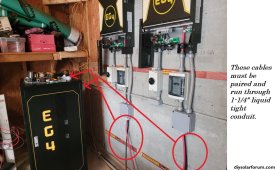
Here's what I've got so far, but I need to put the cables in 1-1/4" flex tubing, and the run falls too short with single 84" lines. If things won't overhead, I'm thinking I can pick up from the breakers with full-length 84" 1AWG and make this work. What do you think?
Perhaps I should just switch to the 2/0 cable suggested by Will Prose as shown here: https://www.amazon.com/Welding-Battery-Flexible-Terminal-Connectors/dp/B01M35S1J2

Open to all nature of guidance. Thanks.
 

Attachments

  • Honeyview_20231005_180345.jpg
    Honeyview_20231005_180345.jpg
    454.7 KB · Views: 4
Back
Top