diy solar

diy solar

Wooden battery rack and temperatures

CaliSunHarvester

Solar Enthusiast
Joined
Dec 25, 2022
Messages
471
Location
Santa Cruz, California, USA
Hello, I have a battery bank consisting of 5 identical 100Ah rack batteries from SunGoldPower. I built a wooden rack structure to store them. It looks like this:
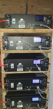
20240201_175002.jpg

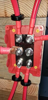
The walls (left/ right) are 2x8s, and each level's floor is from 2x12s. The rack is open at the back and open at the front. There is a bus "bar" mounted each left and right. The batteries are connected with the manufacturer's wires to the bus:
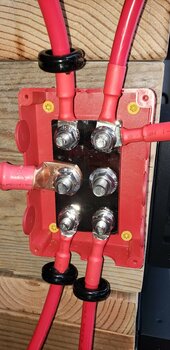
20240102_135355.jpg

I am concerned about the uneven use of the 5 batteries.
IIRC, the one at the top shows 10 cycles and the one at the bottom 8.
Yesterday afternoon, all 5 batteries were "full" (100% SOC) and this morning the SOCs were, in order from top to bottom:

60% / 64% / 68% / 73% / 78%

The temperature that each battery reports for its cells is:

25C / 24C / 21C / 20C / 18C

One can feel with his/her hand that the battery on top is quite a bit warmer on the outside as the one at the bottom.

Is this only because heat rises?
Or is #1 warmer because it delivered twice as much energy as #5 (40% vs 22%) ?

For those who have a conventional metal rack: do you observe something similar?
 
I have 12 batteries, arranged in 2 rows of six. I typically see a 8 degree F difference in battery temperature between the 2 rows with the upper being warmer.
 
There will be a difference between packs at different temps. As little as a 2C difference can make a marked change in behaviours. What you are seeing is not actually all that unusual, given you are starting at 18C at the bottom and finally reaching "optimal" at 25C with the top pack. Ground level is almost always cooler and the lowest ambient temp. If this was on the 2nd floor of a building for instance, that would be a bit different.

Your wiring seems to be correct, in as much that you used a good Block type of bus and equal length wires so that prevents wire bias. I note the chokes (LOL) I bet you ran into some noise - tip, pairing the (+)&(-) together reduces that noise.
 
I note the chokes (LOL) I bet you ran into some noise - tip, pairing the (+)&(-) together reduces that noise.

What is a "choke"? (English is not my native language)

Are you saying connect (+) and (-) directly together? Things would be *very* quiet then, after a brief loud noise, I imagine.

The inverter makes noise, like a dishwasher. This setup is not inside a residence, and very well insulated, so moderate noise doesn't matter.
 
1706986101082.png

I'm just wondering why you doubled up on that top right terminal versus using the other available post?

If you trace those leads back, are they some of the offending off balance batteries?

Also, what does your negative bus bar look like?
 
why you doubled up on that top right terminal versus using the other available post

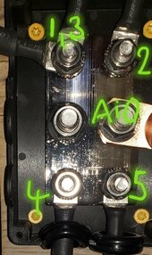
the 4 outer posts are M8, the 2 in the middle are M10. One of the M10s goes to the AIO.

The batteries come with M8 size wire. I was looking at drilling the terminal of the 5th wire out a bit to fit on the M10 post, but there is not much substance to drill. I also thought about making a new wire of the same gauge with an M10 terminal on one end, but then I would worry that the material is somehow different, a 1/10" longer or shorter, the bigger terminal might also carry the electrons better than the 4 smaller ones.

If you trace those leads back, are they some of the offending off balance batteries?
1 and 3 share a post. Wire 3 is mounted under 1.

Negative side is a perfect mirror; I added labels in there:

20240203_110024.jpg
.
 
What is a "choke"? (English is not my native language)

Are you saying connect (+) and (-) directly together? Things would be *very* quiet then, after a brief loud noise, I imagine.

The inverter makes noise, like a dishwasher. This setup is not inside a residence, and very well insulated, so moderate noise doesn't matter.
Pairing wires: Means running both Positive & Negative side x side together, this reduces the magnetic fields generated by DC.
Ferrite chokes--or beads--attenuate high-frequency EMI in a circuit by working as low-pass filters. Only low-frequency signals pass through a circuit.

Noise RFI/EMI is generated by DC wiring thanks to the magnetic fields they carry.
 
Back
Top