1) Do the 1/0 support the same specs as the 1AWG (ie 600 volts /200 amps)?
2) If so, can I use the 3/8" ends on the 5/16 lugs in the inverter?
3) If not, can I use a second set of the 84in 1AWG from my breakers to the battery, or is that going to cause overheating?
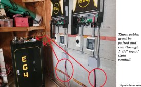
Neither 1/0 or 1 AWG(these are different wire sizes) are rated for 200 amps by the electric code(NEC). For 200 amps you will need 3/0 or 4/0 AWG conductors, 2 1/0 AWG in parallel would also be acceptable. Ref: NEC 2020 310.16 Ampacities of Insulated Conductors in Raceway, Cable, or Earth (Directly Buried) You should use a NEC acctable conductor type like MTW, RHW-2, etc.
Lug size should match the bolt size
1 AWG is not large enough to run in parallel.