JahneTheron
New Member
- Joined
- Sep 17, 2022
- Messages
- 25
@JahneTheron we also need pictures of the ac distribution panel
Also we need pictures of the dc2dc charger with the covers over the wiring terminals removed.


@JahneTheron we also need pictures of the ac distribution panel
Also we need pictures of the dc2dc charger with the covers over the wiring terminals removed.
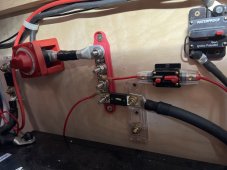
If there is no negative wire going to the starter battery then we must look for one going to the frame, either from the negative busbar or from the dc2dc charger common.Here’s the way he attached to battery. One cable running straight to positive.
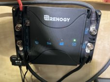
We need to see the dc2dc charger terminals which means you need to remove the covers over the terminals.It comes out the bottom left of the solar charger - goes to a fuse then onto the positive of vans (lead acid battery?) Is this ok?
Sorry, what are you taking the covers off?I’ll take the covers off 12vlt DC input just need to get my impact

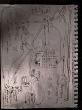
Does that wire terminate on the negative busbar? - yes, if you're looking straight at the round holes on front Invt charger, its the bottom left one (see diagram I drew out).It appears that the inverter_charger chassis ground terminal has a wire connected to it.
Does that wire terminate on the negative busbar?
Is there a wire from the negative busbar to the frame?
If yes, what awg is it?
How many wires are coming from the pv panels?
If its 2 then they are un-grounded.
It its 3 then they are grounded.
The AC cord for giving 24 vlt has a plug for using higher power products for short periods.q: what is at the other end of those ac cords?
By AC you mean the shorepower plug wire and and the high power plug coming from DC to DC charger, Im not 100% sure but its thick. Id guess 5 AWGWhat awg is the ac wiring?
Are we not going to talk about the reversed polarity wiring on both AC in and out on inverter?
Ok good so the inverter charger case is bonded to the negative busbar.Does that wire terminate on the negative busbar? - yes, if you're looking straight at the round holes on front Invt charger, its the bottom left one (see diagram I drew out).
That is not good.Is there a wire from the negative busbar to the frame? - There is a neg wire on Negative busbar going to body of van
If yes, what awg is it? -to the frame of van maybe a 12AWG ..
Its fine if its not grounded.How many wires are coming from the pv panels? - 1x Red. 1x Black (from the roof)
If its 2 then they are un-grounded. - how to ground them?
It its 3 then they are grounded. - looks like 1x red, 1x black... ill double check snap pics that too
The inverter is producing 120VAC.The AC cord for giving 24 vlt has a plug for using higher power products for short periods.
Have a look at this chart and see if you can identify it.The other AC cord has a three-prong end to plug into Shore power at RV park or power while parking in someones drive
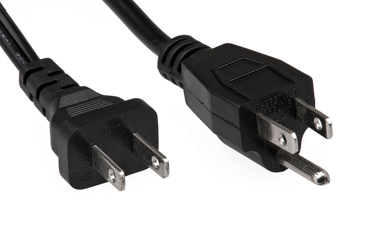
AC stands for alternating current.By AC you mean the shorepower plug wire and and the high power plug coming from DC to DC charger, Im not 100% sure but its thick. Id guess 5 AWG
Thanks for catching that.Are we not going to talk about the reversed polarity wiring on both AC in and out on inverter?
And that black electrical tape is a likely sign of covering up something that shouldn’t be there.