diy solar

diy solar

Installing Sol Ark 15kw CT in Combo Main/Meter Panel

cschill2020

New Member
Joined
Sep 25, 2023
Messages
10
Location
Bay Area, CA
Hi,

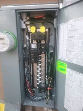
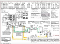
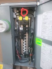
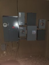
I have been looking at some threads, but didn't find my exact situation.i have a Sol Ark 15kW inverter that I am planning on connecting to a critical load subpanel. My main panel is a combo meter/main 200A: see photo. The meter is attached directly to the 200A disconnect.

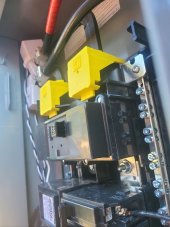
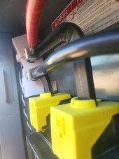
Can I install the CT sensor directly on the bus bar under 200A disconnect. The bus bar does get smaller right at the disconnect, but I may have to pick up the larger 200A CTs... I will be moving some of these breakers to the sub, so there will be more room on the bus.
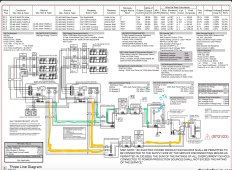
 
As long as the CT's are installed UPSTREAM of ALL the branch breakers in the main panel and there are no other loads attached to your incoming utility wires they will accurately measure NET power coming in or going out.
 
I'm having an issue with my CTs on my stacked solark 12k setup. I paid extra money to get a solar ready panel and solark is telling me that the CTs won't work in this configuration see photos. The two black wires one with red tape is l1 and l2 going to the meter from the inverter The CTs are wrapped around the bus bar after the loads and after the inverter.
 

Attachments

  • 22736.jpeg
    22736.jpeg
    172.4 KB · Views: 30
  • 22735.jpeg
    22735.jpeg
    128.8 KB · Views: 29
  • 22732~2.jpeg
    22732~2.jpeg
    201.7 KB · Views: 28
I'm having an issue with my CTs on my stacked solark 12k setup. I paid extra money to get a solar ready panel and solark is telling me that the CTs won't work in this configuration see photos. The two black wires one with red tape is l1 and l2 going to the meter from the inverter The CTs are wrapped around the bus bar after the loads and after the inverter.
So, is the system working or not?
 
What specifically is the issue you are trying to solve? Looks like a line side tap feeds the inverter(s) and the inverter(s) back-feed the main panel bus bars at the bottom right. The main breaker should be OFF so the inverter is supplying and controlling 100% of the power.
If you are trying to prevent sell-back to the grid the CT's are located correctly, assuming they are completely closed around the bus.
The breaker at the bottom goes to a transfer switch for the subpanel so I can bypass the inverters. It won't pull power from the battery during TOU (demand) running it how you suggest is a good idea however it's doesn't have 200 amp pass through on a 12K.
Solark is looking into a fix. I attached my wiring diagram. I suppose I could just sell from the batteries during demand time.
 

Attachments

  • Screenshot_20231213_160028_Chrome~2.jpg
    Screenshot_20231213_160028_Chrome~2.jpg
    469.2 KB · Views: 11
Last edited:
The non-sell back is not working properly
Ae you confident that the L1 and L2 are correct? Where on the panel does your inverter connect? The TAP or the Bottom right?

Edit to add...it shouldn't matter which side the L1 and L2 are on when it comes to sell back, unless you have an advanced meter that measures both L1 and L2 independently.
 
Last edited:
Ae you confident that the L1 and L2 are correct? Where on the panel does your inverter connect? The TAP or the Bottom right?

Edit to add...it shouldn't matter which side the L1 and L2 are on when it comes to sell back, unless you have an advanced meter that measures both L1 and L2 independently.

The inverter connects where the lugs connect to the bus bar in front of the CTs. The breaker down below to the right is for the transfer switch inverter bypass for the critical loads panel. The CTs seem to add phantom loads to the inverter and it causes me to send battery power past the CTs even though there's no load to compensate for.
 
The inverter connects where the lugs connect to the bus bar in front of the CTs. The breaker down below to the right is for the transfer switch inverter bypass for the critical loads panel. The CTs seem to add phantom loads to the inverter and it causes me to send battery power past the CTs even though there's no load to compensate for.
Sounds like a power loop. Can you draw out each path.
 
Sounds like a power loop. Can you draw out each path.
See attached diagram. Green is the grid side of the inverter yellow is the load side.
 

Attachments

  • Screenshot_20231213_160028_Chrome~3.jpg
    Screenshot_20231213_160028_Chrome~3.jpg
    479 KB · Views: 7
Can you show me where the CTs are located on which string.

*I'm not familiar with the way SolArk CTs work. (Assume its similar to EG4s 18Kpv
Screenshot_20231213_160028_Chrome~3.jpg
 
CTs in this panel implies that you want the inverters to back-feed this non-critial load panel. Is that statement correct?

22732~2.jpeg
 
Nice diagram, but your setup doesn't look like that. Maybe I'm missing something

Sorry trying to mark these up on my phone. The CT location in blue on the diagram attachment is after all the loads before the meter. In the main meter combo panel photo the red circle is the grid input to the inverter which is going to the solar lugs on the bus bar going to the meter.
 

Attachments

  • Screenshot_20231213_160028_Chrome~4.jpg
    Screenshot_20231213_160028_Chrome~4.jpg
    481.5 KB · Views: 9
  • 22732~3.jpeg
    22732~3.jpeg
    202.6 KB · Views: 9
  • 20231120_185330.jpg
    20231120_185330.jpg
    89.5 KB · Views: 6
Last edited:
Sorry trying to mark these up on my phone. The CT location in blue on the diagram attachment is after all the loads before the meter. In the main meter combo panel photo the red circle is the grid input to the inverter which is going to the solar lugs on the bus bar going to the meter.
Why did you wire your panel as a critical load and a non-critical load. As shown on your diagram?

Edit. Ok I understand now. It should work that way you have it.
 
Back
Top