Jesshaines
New Member
- Joined
- Mar 29, 2022
- Messages
- 36
Ok, here's my latest obstacle/troubleshooting challenge...
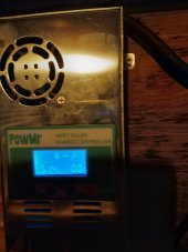
I have a power Mr 60 amp charge controller, with 48 volt 16 cell battery.
I've had two panels connected for the last week or so with no issues. Well let me correct that - but more on that later.
Power Mister has two terminals for panel connection. Today I tried to wire a third panel into the second terminal pair I hadn't been using so far.
I put a breaker on the circuit and when I switched it on, a short time later I noticed a big dip in battery voltage. Checked the BMS and it appears the panel was pulling around 8 amps.
I know this can potentially be caused by failed diodes. So I switched to another panel, but the same problem.
I've checked and rechecked wiring polarity. I'll do some testing on the panels tomorrow, but I'm beginning to doubt that is the issue and for now I can't let my brain rest!
So one idea I had was to check at the mc4 connector coming out of the charge controller for voltage there. I found battery voltage which surprised me. So I checked the lines to the panels that have been working fine for 2 weeks, also battery voltage.
Is that normal?
2nd issue - on my "turn on day" 2 weeks ago, when I initially closed the circuit to the panels, nothing happened. The charge controller showed no input voltage or watts.
I won't make excuses for myself.... I became convinced that I'd reverse polarity and switch the lines around. When I close the breaker that time it immediately tripped the breaker.
I went back to how I originally had it (after pulling those two panels which definitely have blown diodes and are probably fried. Sigh. Well if the worst that happens to me on the solar adventure is too fried panels I'll count myself lucky and grateful).
This next time, everything seemed to work fine and this is the setup that's been charging my battery for the last 2 weeks. BUT - at night power Mr always reads battery voltage on the screen when there's no input.
Well if anyone read this far I'd be grateful for any advice or experience. Or just a bit of encouragement you got this keep going you'll figure it out!
I know this is a long story for a single question but I mostly wondering about battery voltage at the ends of the lines coming from the charge controller to the panels. That seems really weird. Anyone know if that is remotely normal?
Thanks