diy solar

diy solar

Inverters don't have enough voltage/amps

radycal

New Member
Joined
Feb 10, 2024
Messages
2
Location
maine
I have a 3 panel, 2 battery 12v system I did on the cheap to light up some camping cabins. Panels in parallel. Extension cords were used to juice up cabins with 12v lights and charge ports. Everything works great. Then I get the idea to add a small inverter (300watts) to each cabin. Any load, even an 75 watt bulb crashes the inverters. I guess it's because they are too far from the batteries or maybe wire size. The run from my solar shack to the cabin #1 is 40 feet, then another off that one that's 20ft long to cabin 2. I feed directly from batteries not the load tap on the charge controller.

Is there anything I can do to deliver more juice to the cabin inverters by beefing up the lines or would I be better just running AC lines from my 3000 watt inverter in the solar shack (It will run a table saw). But will I lose power there too. Just want enough AC for people to charge laptops and run a fan. Thanks!
 
The practical wire "round trip" distance for a 12 volt system from the batteries to the load or inverter is around 10 - 15 ft max, and 5 ft is better. Your description is 80 - 120 ft.

The longest run of 120 vac that I have done personally is to use a pair of 50 ft, heavy, 10 awg extension cords from mcmaster to run a modest load like you are doing. I am sure that others have done more, but voltage drop starts to kick in.

I guess that in your position, I would set up one solar panel, battery and inverter in each camping cabin. Just mount the panel vertical on the south wall of the cabin in a sunny place.

You can use 10 awg wire for all of it.
 
Your DC runs should always be as short as possible to an inverter.

So, yes, you should put the inverter in the shack where your batteries are and directly connect the batteries to the inverter and then run new AC only wiring to the cabins.
 
You could buy some direct burial 14/2 wire and run the 120V from the shack inverter to outlets in the cabins. Make sure you install a breaker rated for 15 amps and put GFCI breaker outlets in the cabins. Dig down to 18" deep trench if you want to make it even nicer drop some gray PVC conduit in the trench run the wire in that if you want. You can find 100 feet of underground wire for $56 on ebay. If you know a electrician maybe you do all the work just have them check it over.
 
A 300w, 12v inverter uses about 25-30A EACH at full load (and likely to spike more when connected)
Even a 75W light bulb running through the inverter is 6.6A at 12v
I don't know the size of your extension cords (mains I assume, being used on 12v), they are usually about 1mm^2 (I work in metric lol), the 'heavy duty' ones are usually 1.5mm^2
You have a 12m/40ft run and then a 6m/20ft run that makes 18m/60ft total with 2x 300w inverters hanging off it- assuming 75w bulbs with one on each, thats 150w at 12v = 12.5A approximately...

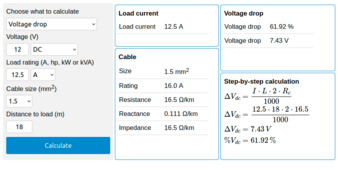
The results don't look good- I ran them through the Au/NZ voltage drop calculator I usually use and...
1707602479129.png
Most of that can be ignored- but a 61% voltage drop???
Your voltage with just one 75w lightbulb on each inverter is horrendous...
Over half of the voltage is being lost as heat on the way to the two inverters...

No wonder they are shutting down...

Your cables simply aren't up to the job...


You could run the inverters at the battery bank, and just run mains to each, or replace the cables with much heavier cables (thats going to be pricey, but safer)
 
Either a separate system at each location or a central system sending the higher voltage AC over thick wire to the locations. A 5% voltage drop on 12v is 10x worse than a 5% drop over 120v.
 
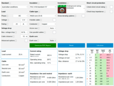
To give you an idea- to keep the voltage drop under 3%, using the two 300w inverters at full power ie 300w load a larger laptop and a couple of phones could reach that)- you would need a minimum of 50mm^2 cable- thats 1/0AWG...
(note that although the 50mm^2 or 1/0AWG is rated at 150A maximum current carrying capability, and we are only pulling 25A- it is not the maximum current carrying ability we are interested in here, but the voltage drop- bigger cables have less voltage drop (if you look at the bottom right of the picture below, you will see how much voltage drop is present on each size cable for the installation shown at the top (two cables buried underground in this case)
1707636497300.png

For those wanting to play around with various settings, it can be found HERE (note it defaults to Australian mains (230v) initially but you can set it to anything you want)
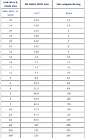
Converting mm^2 to AWG

1707637171917.png
 
Last edited:
Back
Top