jim furlong
New Member
- Joined
- Jun 19, 2020
- Messages
- 61
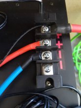
Thx for that bit of info. I should get in to the habit of using bus bars... I currently just have the batteries in parallel with a positive connection going to the all in one inverter/charger (mpp solar lv6548) from one battery and the negative lead going to the inverter from the other batteryRemember that the cables going to the inverter needs to carry twice as much current as the cables between the batteries. If your intent is to add more batteries in the future do not continue to connect in this manner. Instead use a star configuration with all positive battery terminals connected to a common positive bus bar, and same for the negative terminals. Then heavier cables from the busbars to the inverter and charge controller. Breaker (+) and ammeter(-) go in series with those heavier cables.
I do notice that the current between the 2 batteries is different 7.3A on positive and 12.4 A on the negative. How ever the current going to the inverter from the batteries is equal on both leads 20.5A
Why is this ? I think they should be much more equal

Any thoughts on that would be greatly appreciated