diy solar

diy solar

JBD 200A BMS Settings Sanity Check & Voltage Calibration

crawdude

New Member
Joined
Jan 22, 2022
Messages
14
Super excited that I finally got my battery assembled and BMS hooked up! This was a pretty intimidating undertaking but there's so much good information on this forum that helped me figure it out! I'm getting ready to do my capacity test but I want to get my BMS fully configured for my 4s 304Ah 12V pack. I read through quite a few posts for the settings and think I've gotten most everything but just want another set of eyes before I run my test!

Question 1: Do I need to calibrate the voltage in the Xiaoxiang app?
I top balanced all the cells in parallel with a 10A supply. I set the voltage on the supply to 3.58V as I was reading 3.65V on my multimeter (#1). I reassembled the pack in series and connected the BMS to prepare for the capacity test. When I first connected the pack the Xioxiang app read ~3.581-3.583V/cell and the multimeter read 3.63-3.64V/cell.

My present voltage readings:

Cell #Xiaoxiang App VoltageMultimeter #1 Voltage (~7 yr old)Multimeter #2 Voltage (>10 yr old)
13.5693.6123.59
23.5693.6123.59
33.5683.6113.59
43.5753.6163.60

Thoughts on calibration?

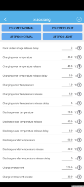
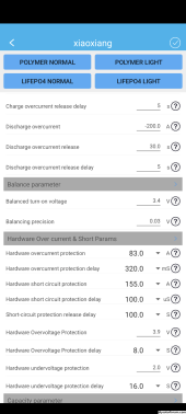
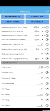
Question 2: Could someone look at my settings and let me know if I'm missing anything?
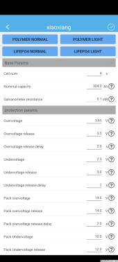
Screenshot_20231126-234901.pngScreenshot_20231126-234914.pngScreenshot_20231126-234927.pngScreenshot_20231126-234937.png
 
Agree with SeaGal. If two say the same thing...

Also, the Supply and BMS are designed to read voltages in that range with precision. The multi-meter is probably not. The difference is about 1.4%, which is probably within the error range of the multi-meter.
 
If your power supply said 3.58V and the BMS says 3.58 and your multi-meter says 3.65V, I'd throw the multi-meter in the bin and buy a new quality one (Fluke or similar).
Maybe I'll go pick a new one up, looks like my local hardware store is running a sale.

Just wasn't sure what to trust since the power supply was a cheap Amazon one and my multimeters were old!
 
Agree with SeaGal. If two say the same thing...

Also, the Supply and BMS are designed to read voltages in that range with precision. The multi-meter is probably not. The difference is about 1.4%, which is probably within the error range of the multi-meter.
Thanks for you input! I'll wire everything back in parallel and finish the top balance then!
 
How old are the batteries in your meter?
Good point! I changed the batteries and result was still the same.

I went and bought a Fluke and it verified the accuracy of the BMS and the power supply. I just put everything back in parallel to finish the top balance before the capacity test.

Thank you everyone for your help!
 
I went and bought a Fluke and it verified the accuracy of the BMS and the power supply.
Phew... I worry sometimes when I suggest something in case it didn't work out!

I swear by my 30+ year old Fluke (I also swear at it sometimes when I forget to move the probe from the A connector back to the V connector)... but good to know it's working - hope it gives you 30+ years service too :)
 
Didn't you learn from your earlier incident ?.
nick-lutsko-nick.gif
 
but there's so much good information on this forum that helped me figure it out!
Hmm...

I want to get my BMS fully configured for my 4s 304Ah 12V pack.
I top balanced all the cells in parallel with a 10A supply.
Four 304Ah cells connected in parallel for top-balancing yield an eqwt. LFP Cell of 4 × 304 = 1216 Ah @ 3.2V.
Charging this 'BIG' Cell with a 10 Amp Supply results in a C-rate of 10 Amps / 1216 Ah = ~0.008 C.

Assume your battery datasheet specifies a charge termination condition of 0.05 C @ 3.65V, you will need to monitor and disconnect the power supply once Cell voltages have risen to ~3.425 V @ 10 Amps CC.

Manufacturer-specified termination condition3.65V @ 0.033C3.65V @ 0.05C
Cell voltage (V)Termination current (C)Termination current (C)
3.370​
0.000​
0.000​
3.400​
0.004​
0.005​
3.425​
0.006​
0.010​
3.450​
0.009​
0.014​
3.475​
0.012​
0.019​
3.500​
0.015​
0.023​
3.525​
0.018​
0.028​
3.550​
0.021​
0.032​
3.575​
0.024​
0.037​
3.600​
0.027​
0.041​
3.625​
0.030​
0.046​
3.650​
0.033​
0.050​

Table Courtesy: https://nordkyndesign.com/charging-marine-lithium-battery-banks/

Setting DC power supply to 3.65 V and letting the current drop to zero is the fundamental mistake people do here while top balancing their factory new cells. And quite unfortunately, I've yet to see anyone else on this entire forum having figured out this extremely simple thing.
 
Hmm...


Four 304Ah cells connected in parallel for top-balancing yield an eqwt. LFP Cell of 4 × 304 = 1216 Ah @ 3.2V.
Charging this 'BIG' Cell with a 10 Amp Supply results in a C-rate of 10 Amps / 1216 Ah = ~0.008 C.

Assume your battery datasheet specifies a charge termination condition of 0.05 C @ 3.65V, you will need to monitor and disconnect the power supply once Cell voltages have risen to ~3.425 V @ 10 Amps CC.

Manufacturer-specified termination condition3.65V @ 0.033C3.65V @ 0.05C
Cell voltage (V)Termination current (C)Termination current (C)
3.370​
0.000​
0.000​
3.400​
0.004​
0.005​
3.425​
0.006​
0.010​
3.450​
0.009​
0.014​
3.475​
0.012​
0.019​
3.500​
0.015​
0.023​
3.525​
0.018​
0.028​
3.550​
0.021​
0.032​
3.575​
0.024​
0.037​
3.600​
0.027​
0.041​
3.625​
0.030​
0.046​
3.650​
0.033​
0.050​

Table Courtesy: https://nordkyndesign.com/charging-marine-lithium-battery-banks/

Setting DC power supply to 3.65 V and letting the current drop to zero is the fundamental mistake people do here while top balancing their factory new cells. And quite unfortunately, I've yet to see anyone else on this entire forum having figured out this extremely simple thing.

I'll have to reread that link a couple times to absorb the information, not fully understanding it.
 
Tongue testing PP3's should be a pre-requisite to being a DIY Solar Forum member ? ?
 
Back
Top