diy solar

diy solar

JBD 4S 200A BMS in Parallel

billh1986

New Member
Joined
Oct 8, 2021
Messages
11
Hi, My goal currently is to have 300A to 400A to power a Renogy 12V 3000 to 6000W inverter. What I have now is a 100A JBD on 4 280A cells and a 100A Daly on another set of 280A cells. I used the current setup for about a week and it worked fine up to about 2000W.
I have ordered 2 more sets of batteries and 3 200A JBD BMS's. I just found out from the manufacturer that you can't use the 200A BMS in series or parallel.
Since one 200A BMS will not give me the 400A I need, I appear to have 3 coming that I can't use.
I understand why you can't connect some BMS's in series due to the voltage but why would it not work in parallel.
Anyone have any experience with this?
 
There are many batteries that do not allow parallel configurations. It has to do with backfeed I think.

Usually, there is a limit number in place, like, no more than 4 in parallel, or, all in parallel must be identical specs. I do not remember.
 
There are many batteries that do not allow parallel configurations. It has to do with backfeed I think.

Usually, there is a limit number in place, like, no more than 4 in parallel, or, all in parallel must be identical specs. I do not remember.
The manufacturer rep said only the JBD 50a to 100a BMS's worked in series or parallel. Looks like I'll be reselling 3 200a BMS's. Eventually, I will be rebuilding to 24v or 48v where this won't be a problem, however, that requires replacing my $1000 inverter. Maybe next year.
 
There are many batteries that do not allow parallel configurations. It has to do with backfeed I think.

Usually, there is a limit number in place, like, no more than 4 in parallel, or, all in parallel must be identical specs. I do not remember.
Can you please explain further? I assume, with backfeed you refer to some unwanted back and forth charging/discharging between batteries.

Can this be controlled by controlling the charge MOSFET on a smart BMS? I think along the lines of preventing charging of two batteries out of a three-battery-system. And this then switching through the three batteries.
 
The manufacturer rep said only the JBD 50a to 100a BMS's worked in series or parallel. Looks like I'll be reselling 3 200a BMS's. Eventually, I will be rebuilding to 24v or 48v where this won't be a problem, however, that requires replacing my $1000 inverter. Maybe next year.

I can personally attest to the fact that the 150 amp JBD units work in parallel. Just make sure that the batteries are in the exact same state of charge (top balanced, and rested) when you connect them. I have had two of them in parallel for over a year now with no problems.

I tested the same configuration with JBD 120a units as well and got the same result.
That's good to hear. I do intend to at least try them in parallel. Unfortunately, they are all on a boat in San Francisco waiting to get unloaded. Won't see them till sometime next year:(

Thanks for the input.
 
Can you please explain further? I assume, with backfeed you refer to some unwanted back and forth charging/discharging between batteries.

Can this be controlled by controlling the charge MOSFET on a smart BMS? I think along the lines of preventing charging of two batteries out of a three-battery-system. And this then switching through the three batteries.
My guess n this is the mosfets in the 200A version cannot handle enormous amperage potential of a paralleled bank of 200A batteries.
Likely the “no parallel” rating is a cya on their part to prevent liability of fire if several 200A banks get put in and issues happen.
 
My guess n this is the mosfets in the 200A version cannot handle enormous amperage potential of a paralleled bank of 200A batteries.
Likely the “no parallel” rating is a cya on their part to prevent liability of fire if several 200A banks get put in and issues happen.
That is my guess as well. However in my case, all banks are balanced, equal charged, fused and the max combined charge current won't exceed 150A. Also, a possible peek discharge of 400A divided over 2 to 3 banks would be a very rare occurrence.
 
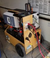
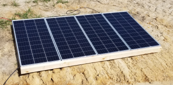
Currently I have 2 banks of 4 280a cells. One is using a 100a Daly bms, and the second is using a 100a JBD. With 4 panels, I was able to work a small building project for almost 2 weeks with no gas generator backup. This unit had little to no problem putting out 200a however the inverter can draw 400a which would be a problem. this is the reason for the 200a BMS's I ordered.
 

Attachments

  • solar.jpg
    solar.jpg
    317.7 KB · Views: 49
  • panels.png
    panels.png
    1.6 MB · Views: 46
CRAP - can anyone confirm this... I just ordered 2 of them a few days ago. kinda the same situation...

 
I can personally attest to the fact that the 150 amp JBD units work in parallel. Just make sure that the batteries are in the exact same state of charge (top balanced, and rested) when you connect them. I have had two of them in parallel for over a year now with no problems.

I tested the same configuration with JBD 120a units as well and got the same result.

Similar experience to mine. Two 120 amp 4s BMS. No issues that I can tell. The batteries stay fairly well in sync.
 
Similar experience to mine. Two 120 amp 4s BMS. No issues that I can tell. The batteries stay fairly well in sync.
thank you... I was worried, even though i couldnt think of a reason they wouldnt work
 
My guess n this is the mosfets in the 200A version cannot handle enormous amperage potential of a paralleled bank of 200A batteries.
Likely the “no parallel” rating is a cya on their part to prevent liability of fire if several 200A banks get put in and issues happen.
Not sure if I got this right ... why do you expect that the MOSFETs of each BMS can not handle the amperage? IMHO the MOSFETs are supposed to protect the cells also from a short by switching off. So if there would be an "enormous amperage" (e.g. because all but one BMS already switched off), then the remaining BMS would also switch off, wouldn't it?
So the only reasonable explanation I could come up with would be to prevent inter-battery currents. And this should be manageable by controlling the Charge/Discharge MOSFET ...

Or did I make a wrong turn in my line of thought?

I ask that specifically because I have three 16S 100A DALY Smart BMS controlling 200Ah cells in one bank for meanwhile half a year in basically low power usage. I charge with maximum 10A (from a solar charger) and draw around 2A constantly. As I live in southern Germany, I have quite many cloudy days in a row so the batteries go down to less than 50% SOC occasionally.
And that is when I found problems: As all three batteries float, they won't reach balancing status for quite a while which depletes the weaker cells significantly (W.C. was >500mV difference between cells in one battery). Therefore I am working on a script to switch on and off the MOSFETs of each individual BMS to take care of this (e.g. preventing one battery from discharging to keep it in balancing status). Problem might be, that DALY BMS only balance while charging ... will see.
 
Damm, i've got 2 of these 200A JBD units to parallel two 304 ah packs.

still waiting for cells.

I thought i'd read somewhere that they could work in parallel, just not in series
 
This is from the JBD 200a manual

1) This management system cannot be used in series.
2) When multiple battery packs using this management system are connected in parallel, ensure that the maximum voltage difference of each battery pack is lower than 3V before paralleling.
3) When multiple battery packs using this management system are used in parallel, the total charge impulse current of the adapter may be applied to a single battery pack. It should be ensured that the
total charge impulse current of the adapter does not exceed the maximum value of the charge impulse current of a single management system.


I have no issues with running these in parallel, as i won't be drawing more than 150amps from both packs
Well, this sounds reasonable to me!

Maybe the "Do not use in series or parallel!" statement is just to scare people off to avoid trouble later on. Which of course makes sense, because when dealing with these amounts of energy you'd better know what you're doing! An arc burns for quite a long time with these batteries ...
 
I mean the reality is using in parallel should not be a problem even if there are currents coming between the two paralleled packs each individual BMS would handle how those currents would be applied to the other battery

Furthermore electricity follows the path of least resistance much like water.. ask the roof on my house in the city about that one

So the reality is the currents going to go where it can be used if you have a major disk balance between the two packs sure some is going to transfer to it but even then it shouldn't be an issue the maximum allowable charge rate is 200 amps and the maximum allowable discharge rate is 200 amps so worst case scenario they should equalize between each other

But most likely this won't come into play as they'll probably be pretty closely matched to begin with

Furthermore the only issue that I can really think of would be if one of your bms's shut off under high load let's say you were pulling 450 amps between the two batteries... In theory the pair of bms's should be able to sustain this for a short period of time but what will likely happen is one of them will be triggered and it will shut down to protect itself from overcurrent then immediately all that load will be transferred to the other BMS which will in theory shut down as well

The problem comes to if it will shut down immediately or cause damage before it shuts down to the second BMS and that's the part I don't know and truthfully the Chinese manufacturers probably don't know either

But I think of it this way there is a common misconception that you cannot have parallel conductors coming off of One battery Bank to feed a single load most people have cited that you'll never get them cut exactly the same so there will always be a mismatch and that one side will always be feeding more than the other

Of course this is just hogwash

This is commonly done with the use of parallel conductors going from battery to load... We also see similar things done with people paralleling solar charge controllers again no issues providing you don't exceed the charge current that the battery is happy with

In this case it's just parallel batteries each being fed by a BMS

So obviously there's going to be some minor mismatch in the resistance of the conductors feeding each bms... And some minor differences in the battery Banks and minor differences in the BMSs themselves but the reality is this will Auto balance itself, naturally

So as temperature increases, so does resistance resistance of course slows down the current flow so what will happen is even if there is an imbalance between the two batteries the one that has a higher resistance will give off slightly less current than the one that has less resistance as the temperature increases due to the increased load on the one that is transferring more current, it's resistance will go up causing more current to be transferred to the other battery that before had less current

Of course as current goes away from one or the other battery due to being offloaded to the other bank the temperature will decrease which of course will cause the current to go back up on that side meaning, that both sides will essentially dance back and forth

Keep in mind the current differences were talking about should be very minimal but they're there nonetheless
 
I can't get my head wrapped around how a BMS would even know that it's paired up in parallel? I can understand the series configuration but in parallel, we all know that each battery will handle up to it's limit. I'm sure I'm missing something, but at the moment, sounds like a lot of "we don't know why, just don't" going on. Because the paralleled batteries aren't going to share more amps than what the load is drawing.
 
Back
Top