


You are using an out of date browser. It may not display this or other websites correctly.
You should upgrade or use an alternative browser.
You should upgrade or use an alternative browser.
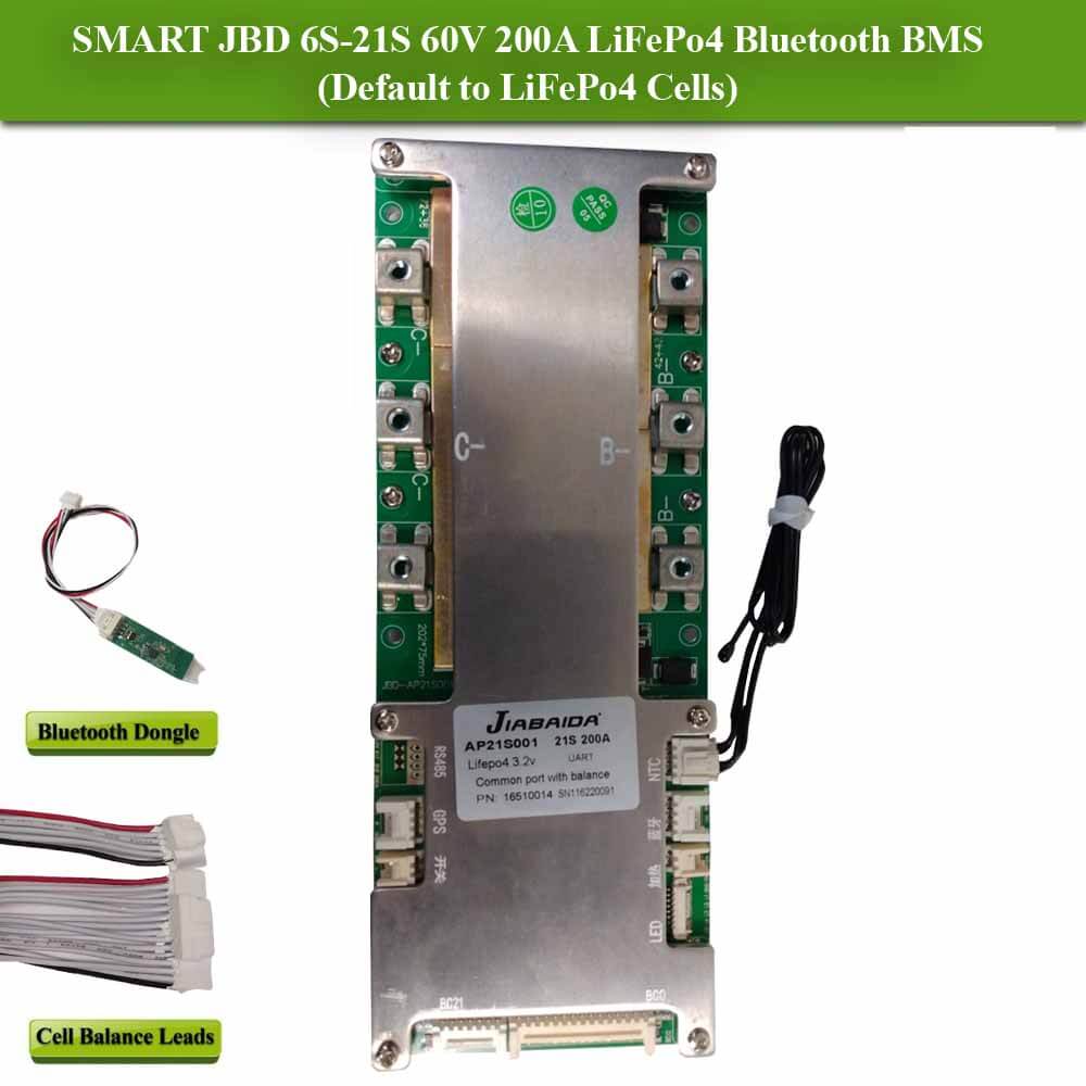
JBD BMS AP21S001
- Thread starter cajocars
- Start date

FilterGuy
Solar Engineering Consultant - EG4 and Consumers
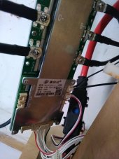
Could you provide a link to where you purchased it?I’ve just received this BMS, however it only has two connectors for B- and two for C-
The shop and the manual pictures show 3 of each
Is this an issue?
View attachment 121799
Without knowing a bit more it is hard to say whether two connections is a problem. However, My guess is that it is not a problem.
It is a 200A BMS so on average, each connector will need to handle 100A. The connections look like they take an 8 mm (maybe 10mm?) screw so I would think a properly crimped cable on each would be sufficient. (Please verify the size of the connection)
Note: You could get away with 4AWG marine 90deg C wire on each, but I would probably go to 2AWG.
I bought it from hereCould you provide a link to where you purchased it?
Without knowing a bit more it is hard to say whether two connections is a problem. However, My guess is that it is not a problem.
It is a 200A BMS so on average, each connector will need to handle 100A. The connections look like they take an 8 mm (maybe 10mm?) screw so I would think a properly crimped cable on each would be sufficient. (Please verify the size of the connection)
Note: You could get away with 4AWG marine 90deg C wire on each, but I would probably go to 2AWG.

JBD BMS for LiFePO4 (with Bluetooth) - 16S 48V 200A
The JBD 16S 48V 200A BMS offers a powerful LiFePO4 battery management solution, enabling you to manage, optimise and maintain the performance of your lithium cells. UK Stockists. Next Day Delivery.
 www.fogstar.co.uk
FilterGuy
Solar Engineering Consultant - EG4 and Consumers
Very Interesting. The link to the add says '200A' but if you zoom in on the picture the label says 150A.

However, I found this site that has a 200A that looks like your board:
 srikobatteries.com
I poked around some but could not find a site selling a 200A JBD that looks like yours.
Furthermore I could not find either of the boards on the JBD site. (But they make a lot of boards they sell to companies so this may not mean anything.
I also notice that the 150A board seems to have some copper plate soldered onto the board to spread all of the current but the 200A model seems to use the brackets for the connectors for distributing the current.
My guess is that they rolled the layout and you have a newer version of the product.
Bottom line: I think you are OK with the two connectors you have on the board.... but that is just my educated guess.
However, I found this site that has a 200A that looks like your board:
Jiabaida (JBD) Smart BMS Lifepo4 200A 6s 7s 8s 10s 12s 13s 14s 15s 16s 17s 20s 21s Battery Protection Module with Balance Leads and Bluetooth Dongle BMS for 18650, 32650, 21700, Prismatic cells.For any lithium battery applications including solar, RV
This is a universal BMS which can be used for Li-ion/Lifepo4//LTO Cell Chemistries. It can be used for many battery pack configurations including 6s 7s 8s 10s 12s 13s 14s 15s 16s 17s 20s 21s Wiring Diagrams for different battery pack Configurations are available at srikobatteries.com website...
srikobatteries.com
I poked around some but could not find a site selling a 200A JBD that looks like yours.
Furthermore I could not find either of the boards on the JBD site. (But they make a lot of boards they sell to companies so this may not mean anything.
I also notice that the 150A board seems to have some copper plate soldered onto the board to spread all of the current but the 200A model seems to use the brackets for the connectors for distributing the current.
My guess is that they rolled the layout and you have a newer version of the product.
Bottom line: I think you are OK with the two connectors you have on the board.... but that is just my educated guess.
FilterGuy
Solar Engineering Consultant - EG4 and Consumers
Do you have a link to the manual?the manual pictures show 3 of each
Do you have a link to the manual?
FilterGuy
Solar Engineering Consultant - EG4 and Consumers
OK..... Is this just a case of them being honest?? 

you have update model new modelI’ve just received this BMS, however it only has two connectors for B- and two for C-
The shop and the manual pictures show 3 of each
Is this an issue?
View attachment 121799
Last edited:
FilterGuy
Solar Engineering Consultant - EG4 and Consumers
Yes.So is this BMS suitable for a solar inverter?
Not really. Having communication between the BMS and the inverter is nice in that it can create central control and central data management, but it is not necessary to have communication. You can build a fully functional and reliable system without it.Does the inverter even need to communicate with the BMS?
FilterGuy
Solar Engineering Consultant - EG4 and Consumers
Not quite.So the BMS just disconnects the battery whenever it’s full and the inverter is charging it or when it’s discharging and it gets to a low SoC?
The inverter will just sense this ‘open circuit’ and interrupt charging and discharging?
The inverter should be set to a charge voltage that is below the disconnect voltage of the BMS. With that, the inverter will charge to that voltage and stop charging before the BMS disconnects the charge current.
On the other end (discharge), the inverter should be set to shut down at a voltage that is higher than the BMS will shut down. That way, the inverter will quit discharging before the BMS disconnects discharge current.
In a well-tuned system, the BMS will never disconnect on charge or discharge. Its role is to act as a second line of defense that kicks in if the system misbehaves or one of the cells goes out of whack.
Understood; given the pretty flat voltage vs capacity curve in LiFePo4 battery and the voltage drop in the wires due to high currents, is the inverter able to continuously read the correct voltage or does it need to pause periodically and assess the voltage? Does the inverter do Coulomb come counting?

Sorry, what is you picture showing? is that you accessing the bms info through a web page or is that the inverter communicating with the bms?you can see remote comm is posable with out Rs485 and only blue tooth or uart adapter made by jbd from amazon. driver work as installed
Similar threads
- Replies
- 4
- Views
- 335
- Replies
- 14
- Views
- 813