diy solar

diy solar

JBD BMS Wi-Fi Module

I urge caution when using the link you sent in Aliexpress. They look like the ones I got from Amazon:


Which more than likely damaged 2 of my BMS. Looking on the board near the UART logic, a resistor overheated and cooked. One of the BMS still works, however, the UART has issues and unless I hit it back-to-back every 30s, the ESP needs reset before I can use it (like the BMS has gone to sleep or something). It only did it on the 2 BMS that I tried these voltage regulators on (I thought "cool! direct to 3.3! no lines to cut, and no pads to solder"). On all the other BMS that I have, they have no problem with the buck converter with the inductor.

Now, it could be that I just had 2 bad BMS and it was coincidence that the only 2 I had issues with were the ones I used the regulator I linked above. The price diff between them doesn't make it worth it for me. I had to order 2 more BMS from Ms. Xiao @ JBD.

YMMV, I just wanted to pass that on.

I finally had time to take 2 of these BMS apart to show the damage when using the above regulators

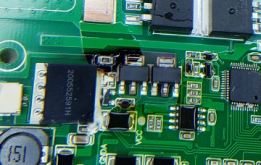
Here are pics of a normal/good BMS (both sides):

1615475250347.png1615475279654.png

Here are pics of one of the ones I used the above regulators on (both sides);

1615475349757.png1615475363506.png

As I said, it could be a fluke that the only 2 I had issues with were the only I used I tried the regulators on, but I didn't want to chance it.
 

Attachments

  • 1615475326375.png
    1615475326375.png
    244.2 KB · Views: 21
Got my JBD bms installed in the tractor now, so I can more safely charge & discharge unattended as a powerwall. At least manually starting discharge, and using a wifi smartplug to enable charging when there is excess solar. Next I want to connect the bms to the rest of my system to monitor it, and add control to discharge automatically.

I'm going to follow your steps melkier for setting up with ESP01, Thanks for posting all your code and sharing! Later I think I'll add another 10s pack which fits perfectly in the front of the tractor, as a paralleled pack with it's own BMS. It will be about 10kwhr total, 8-9 useable.
 
Last edited:
Very cool! Let me know how to works out. Any issues with wifi or the tool, pm me.
 
I have a question for you melkier: do you do anything special for reconnecting each string BMS to the main bank? checking voltage difference between the string and the main bank? Or just manually checking when first connecting each string. Do you have pictures of your powerwall setup, it must be cool?
 
I did not check them when I first built the powerwall as all my batteries came from the same source (and all were the same voltage). However, I did some testing/writing software using a couple of packs and they quickly became "out of sync" with the others. When I re-connected them to the rest of the batts, the current was so high it tripped the breakers. Then, I found out that the BMS over short circuit and discharge protection actually works :) I had 12 other 3.5kWh NMC batts pulling from 1 batt and it really tested my infra. My advice would be to make sure any new batts you introduce are within a few volts of the rest of your system.

I'm moving one of my Sunny Islands right now to another wall (they are very heavy) and the room is a mess atm. As soon as that's done I'll upload a pic for you.
 
Hi, shout out for some guidance please!
I am getting rather annoyed, might be a rather naive question... I want to connect my JBD BMS to my PC...

I have an LLT (JBD) BMS, it has a UART port, this was supplied with a bluetooth board, from this I have deduced which are the RX/TX & gnd pins on the BMS uart connector. rather than fabricating a new lead I split the blue->BMS cable piggy backing the wires RX/TX/GND, and checked the bluetooth still worked... it did.

With the three wires I soldered them to a DB9 pins 2/3 for RX/TX, and 5 for ground, pretty standard. then a USB-> serial connector

in JBD tools, choose the correct com port, 9600,8,1,none (default) and.... nothing. OK first thing reverse rx/tx on DB9... still nothing. loopback test USB->serial with Putty, its fine.

This small step is eluding me! help please

once this is overcome, my shiny new battery is getting Wifi!

Thanks Ian
 
With the three wires I soldered them to a DB9 pins 2/3 for RX/TX, and 5 for ground, pretty standard. then a USB-> serial connector

in JBD tools, choose the correct com port, 9600,8,1,none (default) and.... nothing. OK first thing reverse rx/tx on DB9... still nothing. loopback test USB->serial with Putty, its fine.
Does it work if the BT dongle is removed? can the tx from BMS drive more than one pull up/down resistor (in the BT and what you're adding)?
 
Does it work if the BT dongle is removed? can the tx from BMS drive more than one pull up/down resistor (in the BT and what you're adding)?
Hi, I removed the BT module, so only the serial wire connected... for the very reason you state, and also conflicting traffic.

One thing I did notice is the bluetooth module is an LLT special, and reading the voltages it would have to be to accomodate the Vcc from the BMS. It leaves me wondering if there is something else going on... maybe oscilloscope out time!

Ian
 
When I first got my BMSs (and learning how the serial/UARTs worked), I bought these from Amazon:


I just went outside and hooked it up to my laptop. Definitely crossed TX/RX. Connected GND. Worked fine.
 
Hi, I removed the BT module, so only the serial wire connected... for the very reason you state, and also conflicting traffic.

One thing I did notice is the bluetooth module is an LLT special, and reading the voltages it would have to be to accomodate the Vcc from the BMS. It leaves me wondering if there is something else going on... maybe oscilloscope out time!

Ian

Beware of the Vcc voltage from the BMS ... its 10-12v! It's why I had to use a voltage regulator.
 
Hi Melkier, I was aware the dangers of the VCC, nasty trick that, put my ossciloscope on the rxd and txd lines, they are 3.3v so not enought to trigger my serial to USB adaptor, rummaging in my box of things I have a couple of more recent USB- serial, Now i need to remember what they are... on my way to an answer now. I have plenty of experience in connecting serial devices, always expect to get rxd and txd crossed... mostly lab equipment, but this had me foxed... not met a 3.3v uart before!

Thanks
 
ha in business, update for anyone else struggling with this, the interface you use between the UART and USB must be 3.3v. Having failed with classic USB->serial cables, following Melkiers lead, I dug out a sparkfun FTDI breakout board, the version I have is compatible with both 5v (TTL level) and with a small change 3.3v. with 5v no success, however with the 3.3v modification made the connection has now come to life!

OK, whilst rooting around I also found en esp8226 board..... wifi yay!
 
I was able to cross compile my jbtool binary from linux to windows. It only works for ip (wifi) or serial on windows (no BT support yet), but it does have MQTT support.
Code:
C:\>jbdtool -t ip:10.10.10.10
Voltage                   54.320
Current                   0.000
DesignCapacity            75.000
RemainingCapacity         74.640
PercentCapacity           100
CycleCount                0
Probes                    2
Temps                     22.7,21.3
Strings                   14
Cells                     3.887,3.888,3.886,3.885,3.874,3.879,3.878,3.878,3.880,3.878,3.879,3.880,3.870,3.879
CellTotal                 54.321
CellMin                   3.870
CellMax                   3.888
CellDiff                  0.018
CellAvg                   3.880
DeviceName                15350021-SP15S008C-P14S-100A
ManufactureDate           20201022
Version                   2.5
FET                       Charge,Discharge

For serial
C:\>jbdtool -t serial:COM6
...

To send MQTT data (ip or serial):
C:\>jbdtool -t serial:COM6 -m 10.10.10.1:pack_01:/Powerwall/pack_01

Keep in mind I *just* compiled this ~30m ago so I haven't been able to test fully, but if you dont have linux it might work for you
 

Attachments

  • jbdtool_win.zip
    339.6 KB · Views: 33
is it possible to use an esp8266 uart board to connect to the bms ? maybe with a voltage reg also

Yes ... that's what this project is

 
silly question im sure but everything was detailed except the jbd board purchased/used. is there a specific(aliexpress) variant ? should the uart box be purchased as well as the bms (assuming yes) ?
 
Any BMS with a UART port. Someone contacted me a while back and asked me the same thing as I said "any jbd board" but then he posted a picture and his board did not have a UART port.

You dont need to purchase the bluetooth dongle or any box to plug into uart. You are, in essence, building a wifi dongle here.

For the record, the model I bought is: 15350019-SP15S008C-P14S-100A
 
Back
Top