diy solar

diy solar

JK BMS Active Balancing

jibberishballr

New Member
Joined
Aug 4, 2022
Messages
35
If I'm in the wrong subforum, please redirect me...

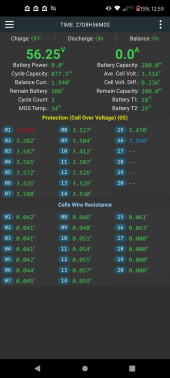
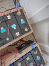
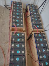
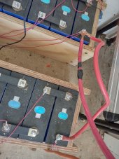
I have two 16cell LifePO4 280ah battery packs connected with 2 200a JK BMS' (b2a20s20p). I've noticed that the voltage between the two is not that close. I have identical settings (at least the ones I could set) in the JK app. There's also some difference between each cell (more than I think there should be). I noticed that battery pack #2 is also showing more cycles than battery pack #1 (but I believe I had battery pack #1 added first).

Trying to understand how to get these more aligned on voltage and how to lower the cell difference in voltage per pack. Let me know if I can provide any more details around the setup.

Any suggestions?

Thanks in advance!


Battery Pack 1 Status and Settings:

Screenshot_20230627-125953.jpgScreenshot_20230627-130138.jpg

Battery Pack 2 Status and Settings:

Screenshot_20230627-125944.jpgScreenshot_20230627-130122.jpg
 

Attachments

  • 1687897122273.png
    1687897122273.png
    356.9 KB · Views: 9
  • 1687897124236.png
    1687897124236.png
    356.9 KB · Views: 9
I have 2 packs with 280ah cells and the same BMSs.

First off I think your start balance voltage is too low. Your packs will try to start balancing while still in the flat part of the charge curve. At the moment, I actually have mine set to start balancing at 3.43v. Once you get a good top balance, your cells should stay pretty well balanced.

If you can leave the discharge off till your cells all get balanced, that would be ideal. Let the BMS do it's job and level everything out. Did you happen to top balance your cells before your wired them all up in series?

As far as the voltage differences between the packs, this could be due to different length cables between the packs and your bus bar or even how your inverter cables are set on your bus bars. Can you share a picture of how you have things all wired up?
Thanks for the advice. I'll try and set the start balancing to ~3.4.

Interesting. I had tried turning "charge" off on the higher voltage pack in order for the lower voltage pack to catch up but you're recommending turn discharge off. Mind giving me some context on that recommendation?

I did not top balance them.

I'll grab an image later on the setup and post here.
 
Something that doesn't make any sense at all is why one pack would be over 3V higher than the other. Are these two 16 cell packs hooked in parallel, or not?
 
First issue is both battery arrays are not balanced. Pack 2 is significantly out of balance.

Set start of balance between 3.40v and 3.45v. Balancing below 3.40v can actually misbalance cells due to random inverter load current upsetting BMS cell voltage measurements for balancing cell selection and balance direction decisions.

Setting balancing above 3.40v pretty much assures you will only balance during charging current as if inverter discharging load randomly shows up, the cells will quickly drop below 3.40v, stopping balancing, while there is moderate inverter discharge current happening.

Once you get balanced, check current balance between two battery arrays at various inverter load currents. Do the comparison when cells are between 90% and 40% state of charging. Should do test in moderate room temp range, 20-30 degs C.

Even if cabling is perfectly matched with all good connections, individual cell overpotential voltage slump with discharge current variation (not perfectly matched cells) will cause some variance in splitting load current equally between battery arrays. Anything between 15% and 20% current sharing mismatch is considered fairly good. This also applies to charging current sharing.

This is an example of what overpotential variance between cells does to current sharing. Each four cell battery array has perfectly matched cells, but the two battery arrays have slightly different overpotential voltage at 50 amps (51 mV at 50A vs. 57 mV at 50A). This is a fairly minor overpotential voltage variation. You will often see more variation than this which increases variance in current sharing.
Batteries in parallel matching.png
 
Last edited:
Interesting. I had tried turning "charge" off on the higher voltage pack in order for the lower voltage pack to catch up but you're recommending turn discharge off. Mind giving me some context on that recommendation?
I'm thinking from the context of balancing your packs. Turn off discharging to let the balancer do it's job and get things balanced before you do anything else. Charging will stop once the voltage reaches whatever your charger is set to but balancing will continue till your cells get within 0.010v of each other.
 
I'm thinking from the context of balancing your packs. Turn off discharging to let the balancer do it's job and get things balanced before you do anything else. Charging will stop once the voltage reaches whatever your charger is set to but balancing will continue till your cells get within 0.010v of each other.
I would not recommend you turn off discharge or charge functions on BMS. They should only be used for specific testing.

BMS will over-ride your disabling once charging or discharging gets above about 3-5 amps to avoid overheating disabled MOSFET's which carries current with its body diode. BMS uses current reading and its flow direction to make the override decision.

When significant current shows up or drops back down there is a time delay enabling and disabling BMS MOSFET's to re-engage or re-override your charge or discharge disable setting.

It can also result in an extra diode voltage drop during top off charging at lower charge currents that can cause your charger to abort absorb charging cycle early, along with the balancing of cells.
 
Last edited:
I would not recommend you turn off discharge or charge functions on BMS. They should only be used for specific testing.

BMS will over-ride your disabling once charging or discharging gets above about 3-5 amps to avoid overheating disabled MOSFET's which carries current with its body diode. BMS uses current reading and its flow direction to make the override decision.

When significant current shows up or drops back down there is a time delay enabling and disabling BMS MOSFET's to re-engage or re-override your charge or discharge disable setting.

It can also result in an extra diode voltage drop during top off charging at lower charge currents that can cause your charger to abort absorb charging cycle early, along with the balancing of cells.
Ok, then turn off/disconnect all loads instead. That way you let the BMS balance without fighting charging and discharging.
 
I would not recommend you turn off discharge or charge functions on BMS. They should only be used for specific testing.

BMS will over-ride your disabling once charging or discharging gets above about 3-5 amps to avoid overheating disabled MOSFET's which carries current with its body diode. BMS uses current reading and its flow direction to make the override decision.

When significant current shows up or drops back down there is a time delay enabling and disabling BMS MOSFET's to re-engage or re-override your charge or discharge disable setting.

It can also result in an extra diode voltage drop during top off charging at lower charge currents that can cause your charger to abort absorb charging cycle early, along with the balancing of cells.
Sooo disable both charge AND discharge? Not just one to play it safe?
 
I have 2 packs with 280ah cells and the same BMSs.

First off I think your start balance voltage is too low. Your packs will try to start balancing while still in the flat part of the charge curve. At the moment, I actually have mine set to start balancing at 3.43v. Once you get a good top balance, your cells should stay pretty well balanced.

If you can leave the discharge off till your cells all get balanced, that would be ideal. Let the BMS do it's job and level everything out. Did you happen to top balance your cells before your wired them all up in series?

As far as the voltage differences between the packs, this could be due to different length cables between the packs and your bus bar or even how your inverter cables are set on your bus bars. Can you share a picture of how you have things all wired up?
Attached images of current setup. Positive and negative run straight to inverters. Let me know if any other details are needed.

Reading these comments, seems like there's some different opinions on how to go about this...what's my safest approach here?

I had one pack running for a few days prior to connecting the second but thought they would be closer in voltage at this point.

I've had batteries set up for 3-4 weeks.

I adjusted starting balance to 3.42 in the app.
 

Attachments

  • IMG_20230628_132219655_HDR.jpg
    IMG_20230628_132219655_HDR.jpg
    232.3 KB · Views: 56
  • IMG_20230628_132153303_HDR.jpg
    IMG_20230628_132153303_HDR.jpg
    215.6 KB · Views: 56
  • IMG_20230628_132209820_HDR.jpg
    IMG_20230628_132209820_HDR.jpg
    224.1 KB · Views: 55
I've found that @RCinFLA has a vast knowledge of electronic components that far surpasses my limited knowledge. So if he says "don't do something, I don't argue".

So even if we don't disable the options in the BMS, I would still suggest charging up the batteries till full (or you get a HVD) and then let them sit for as long as it takes for each pack to balance. You might even want to separate the packs from each other so they can each top balance properly. Once the BMS does it's job and balances the packs out, then try and charge them again to repeat the process. Once you get a good top balance on your batteries, they should stay pretty well in balance as you charge/discharge them.

If you don't top balance (whether that's by paralleling the cells before assembly or letting the BMS do it for you), you're gonna be fighting LVD and HVD all the time due to cell imbalance.
 
The battery cables should be on the terminals first and then add the bms wire, both negitive terminals are wrong( at the bms) and one of the positive terminal is wrong. Another thing is how the batteries are connected to the wires going to the inverter. The positive wire goes from battery 1 to battery 2 in series, then to the inverter, but the negitive wires from the bms are in parallel, then to the inverter. Both positive and negitive wires need to be done the same way. I hope this makes sense, it is hard to explain.
 
Last edited:
I adjusted starting balance to 3.42 in the app.
With a 409 mV delta (pack 2) I would have the active balancer running full time. Maybe adjust the delta to trigger balancing to 25 mV as this will stop the balance in the middle once cells get close.

Even pack 1 has a large enough cell delta (236 mV) to have full time balancing.

Once the cells come within 50 mV at the top will be the time to limit balancing at 3.420+
 
The battery cables should be on the terminals first and then add the bms wire, both negitive terminals are wrong( at the bms) and one of the positive terminal is wrong. Amother thing is how the batteries are connected to the wires going to the inverter. The positive wire goes fron
You cut off here. What's the last part? the positive wire goes from....
With a 409 mV delta (pack 2) I would have the active balancer running full time. Maybe adjust the delta to trigger balancing to 25 mV as this will stop the balance in the middle once cells get close.

Even pack 1 has a large enough cell delta (236 mV) to have full time balancing.

Once the cells come within 50 mV at the top will be the time to limit balancing at 3.420+
Are you suggesting to adjust Balance Trigger Voltage to .025V for both packs?

I've found that @RCinFLA has a vast knowledge of electronic components that far surpasses my limited knowledge. So if he says "don't do something, I don't argue".

So even if we don't disable the options in the BMS, I would still suggest charging up the batteries till full (or you get a HVD) and then let them sit for as long as it takes for each pack to balance. You might even want to separate the packs from each other so they can each top balance properly. Once the BMS does it's job and balances the packs out, then try and charge them again to repeat the process. Once you get a good top balance on your batteries, they should stay pretty well in balance as you charge/discharge them.

If you don't top balance (whether that's by paralleling the cells before assembly or letting the BMS do it for you), you're gonna be fighting LVD and HVD all the time due to cell imbalance.
I think that makes sense. How would I allow them to sit and balance while fully charged if I don't disable discharge on the BMS?
 
Are you suggesting to adjust Balance Trigger Voltage to .025V for both packs?
Yes with such a large differential between cells I recommend full time balance at all voltages charging, discharging and resting.

Once the cells are better in balance the trigger can go back to 10 mV starting at 3.42 while charging only.
 
I recently went through this in build 2p8s 136ah

first I connected all the cells in parallel and waited 24 hours, then I collected 2p8s

the beginning was
Screenshot_2023-06-08-03-19-47-303_com.jktech.bms.jpg

charging my AIO I put 3.45 volts in your case it is 55.2 volts and waited for the cells to balance in my case it was 12 hours

at this time, all consumers were turned off, only charging was in progress

when the cells aligned, I began to raise the charge voltage, with a minimum step of 0.2 volts, my AIO can’t do less, and brought it up to 3.6 volts per cell

later it turned out like this
Screenshot_2023-06-25-00-19-32-675_com.jktech.bms.jpg
when I balanced the settings were like this
Screenshot_2023-06-08-15-44-35-242_com.jktech.bms.jpg
now changed to 0.010 balancing
 
Back
Top