diy solar

diy solar

JK-BMS-CAN with new Cut-Off Charging Logic (open-source)

the metal foil shield which covers every pair of leads has nothing to do (as far as i know) with the metal mesh shield around the whole bunch of twisted twisted pairs.
Only the mesh is connected to the ground clamps of the RJ45 plugs shich might be connected to ground.

The deye inverter is well known to have problems with EMV (EMC?) - so the both "shields" are blocking some of the high frequency emmission the deye is producing
Just keep that in mind - that might be an issue in your case
Sure. But if it is shielded, it is ONLY shielded on the Inverter side.

So I don't see what it should be a problem with my breakout adapter and 30cm of unshielded wires, since the shield is not connected to Earth in your case as well (on the ESP32 side) and while I'm relatively away from the EMC noise source (Deye Inverter).,
ah i see - i thought the breakout board is on the inverter side (which of course does not make sense :p)
was just an idea
 
ah i see - i thought the breakout board is on the inverter side (which of course does not make sense :p)
was just an idea
Exactly.

On the Inverter side I put a virgin and untouched Cat6 SFTP (IIRC) Cable. Exactly to avoid having this kind of issues (plus being lazy to want to crimp a RJ45 shielded connector I guess).

On the ESP32 side it's RJ45 Plug of the existing Cat6 Cable + Breakout Adapter + approx. 30 cm wire somewhat twisted + CANBUS UNIT (CA-IS3050G) + Atom S3 Lite

I was looking to see which exact part I had used for the Breakout Adapter ... cannot find it right now. I thought it was an order on Digikey together with the Atom S3 Lite, but apparently it's not there. Weird ...

EDIT 1: This was the Breakout Adapter I used (on the ESP32 side !): https://www.digikey.dk/en/products/detail/dfrobot/FIT0849/15848077?s=N4IgTCBcDaIIwHYDMAOAtAMQJIBUAMKALAJxoByAIiALoC+QA

EDIT 2: This is the complementary part, for reference: https://www.digikey.dk/en/products/...4IgTCBcDaIIwHYDMAOAtAMQJIBUAMKALOgHIAiIAugL5A
@silverstone: do you set the battery mode to lithium ...etc on the inverter side. Inverter will not send Can activation message if it is not configured to do so!
 
I think the very first thing I will try is to change the CAN settings in the ESP32.

Not sure why @Sleeper85 or @MrPablo have CAN_TX = GPIO5 and CAN_RX = GPIO6 in https://github.com/Sleeper85/esphome-jk-bms-can/blob/main/config/config_atom-s3-lite-esp32-s3.yaml for the Atom S3 Lite.

If you look at the M5Stack it's written RXD = GPIO16 , TXD = GPIO17:
# New: Atom S3 Lite + CAN Hat -> Refer to https://docs.m5stack.com/en/unit/can -> RXD = GPIO16 , TXD = GPIO17

So I have this at the moment in my configuration https://github.com/luckylinux/jk-bm...main/esphome-jk-bms-can/esp32-ble-1.17.4.yaml
YAML:
# +--------------------------------------+
# | ESP32 CAN port pins                  |
# +--------------------------------------+
  # GPIO pins your CAN bus transceiver (TJA1050, TJA1051T or SN65HVD230) is connected to the ESP, note! TX->TX and RX->RX.
  # Old: Atom S3 Lite + CAN Hat -> Refer to https://docs.m5stack.com/en/atom/atom_can -> CAN_TX = GPIO22, CAN_RX = GPIO19
  # New: Atom S3 Lite + CAN Hat -> Refer to https://docs.m5stack.com/en/unit/can -> RXD = GPIO16 , TXD = GPIO17
  # Final: Refer to Sleeper85 GitHub Repository -> https://github.com/Sleeper85/esphome-jk-bms-can/blob/main/config/config_atom-s3-lite-esp32-s3.yaml
  #can_tx_pin: GPIO17 # According to https://docs.m5stack.com/en/unit/can
  #can_rx_pin: GPIO16 # According to https://docs.m5stack.com/en/unit/can
  can_tx_pin: GPIO5 # According to https://github.com/Sleeper85/esphome-jk-bms-can/blob/main/config/config_atom-s3-lite-esp32-s3.yaml
  can_rx_pin: GPIO6 # According to https://github.com/Sleeper85/esphome-jk-bms-can/blob/main/config/config_atom-s3-lite-esp32-s3.yaml

But I think I will try with GPIO16 and GPIO17 now that absolutely nothing is happening.

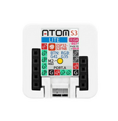
Although it's true that GPIO16 and GPIO17 are not even listed on the Atom S3 Lite itself ...
1711345571615.png

An easy fix will be to upgrade USB cable & Power Supply -> Let's just try with a Raspberry Pi 5V/3A power adapter.

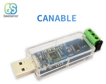
I'll also try, with the same cable and another CAN adapter (CANable Pro), to sniff the traffic, to see if there is something really going on here.
With the can-utils package on Linux, I should be able to do
Bash:
cansniffer -c can0

EDIT 1: The cable I used must also be quite "low-cost". It is "Cat 6 S/FTP" etc. but no AWG indicated. Probably AWG 27 or AWG 28 or something.

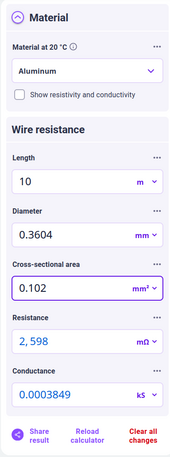
I guess the difference with Ethernet is that the wire resistance plays a much bigger role in CANbus ? I have seen CANbus cablers ($$$$) AWG 22 or AWG 24. In shops, AWG 26 is the best you can buy for Cat 6 etc. Example

But even AWG 27 Aluminum (assuming CCA) the resistance should be peanuts ...
1711347636477.png

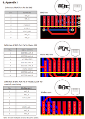
EDIT 2: The BMS CAN Pinout on the Deye SUN-12K-SG04LP3-EU seems correct, Pin 4 & 5 ...
1711348315846.png
 
Last edited:
@silverstone esp32 has 2 uart controller!
S! If can converter is wire to gpio16, 17, it will try using hardware serial. If wire to other gpio, software serial shall be used. So any gpio pair can be ok, i myself use gpio 9 and 10.
In your case i believe your can converter is not activated yet. To try, you can take a tja1050 for uart to test or use a mcp2515 with soi connection!
Most inverters use wire 4, 5 for canH and canL. Deye using that pair as well and you can use a normal cat5 lan cable to test!
It is using pin 4 & 5 but it's not working right now ...

I'll try to sniff using the CANable pro to check the cable connection I guess.

If AWG 27 is too low, I can crimp myself an ethernet cable with AWG23 or AWG24. Solid copper. But it's the rigid/solid/stiff one, not this one used in Patch Cables ...
Do you have any spare can converter? If yes, you can test setting up connection with 2 nodes. Mcp2515 has build in can controller while tja1050 does not. In case of testing you should use 120ohm resistor for can terminating. I doubt your can hat has problem!
 
Do you have any spare can converter? If yes, you can test setting up connection with 2 nodes. Mcp2515 has build in can controller while tja1050 does not. In case of testing you should use 120ohm resistor for can terminating. I doubt your can hat has problem!
Yes I can try with the CANopen on Debian Linux and try to use the cansniff command from can-utils.

To see if the ESP32 is sending something, respectively if the Deye is sending something (one at a time of course).

1711349819457.png
 
I have injected a mcp2515 to capture can mesage and found out that inverter only send 1 can mesage for acknoledgement and does not send back anything at all! Messages on the bus are sent by the battery mostly!
 
@MrPablo, @Der_Hannes, @Sleeper85: on a separate note, I'd appreciate if you could update the GitHub page a bit in terms of configuration.

Instead of just this
1711351459885.png

Maybe make it a Table since there is quite a bit of configuration that is inverter-specific
BrandModelStatusReported byInverter ConfigurationCAN Protocol ESP32CAN Name ESP32Remarks
DeyeSUN-6k-SG03LP1-EUWorkingSleeper85Lithium 00?????????
DeyeSUN-5k-SG03LP1-EUWorkingvdiexLithium 00?????????
DeyeSUN-12K-SG04LP3-EUWorkinglucizeLithium 00?????????
...
 
Last edited:
I have injected a mcp2515 to capture can mesage and found out that inverter only send 1 can mesage for acknoledgement and does not send back anything at all! Messages on the bus are sent by the battery mostly!
So I can only test the cable with the ESP32 alright.

I am not sure where I saw something about BMS_Err_Stop that MUST / MUST NOT be set. Maybe in one of @Sleeper85 / @Der_Hannes posts/github/... ?

I have it UNCHECKED for the time being as I did NOT want to trip ...
 
OK I'm trying to debug with another 10m cable of the same type ... and the CANOpen Pro USB Adapter on the Laptop (Ubuntu Linux).

So the shematic would be:
Laptop Ubuntu Linux <--> CANOpen Pro USB Adapter <--> 30cm twisted wires 0.5mm2 <-> RJ45 Breakout board <--> 10m Cat6 Cable S/FTP (probably AWG 27, not specified) <--> RJ45 Breakout Board <--> 30cm somewhat twisted wires 0.5mm2 <--> CANBUS UNIT (CA-IS3050G) <--> Atom S3 Lite

Code:
Bash:
#!/bin/bash

# Define interface
interface="can0"

# Force interface down
ip link set down $interface

# Wait a bit
sleep 1

# (Re)configure Interface
ip link set $interface type can bitrate 500000 restart-ms 1500

# Wait a bit
sleep 1

# Bring interface up
ip link set up $interface

# Wait a bit
sleep 1

# Sniff CAN traffic
cansniffer -c $interface

Nothing seems to be happening ...
 
Sorry for being less present on the forum, I can't follow all the comments. I read part and @MrPablo and @Der_Hannes answer the questions very well. Important or useful things will be reported in our working group.

I wish you a beautiful sunny day 😉
 
@MrPablo, @Der_Hannes, @Sleeper85: on a separate note, I'd appreciate if you could update the GitHub page a bit in terms of configuration.

Instead of just this
View attachment 204511

Maybe make it a Table since there is quite a bit of configuration that is inverter-specific
BrandModelStatusReported byInverter ConfigurationCAN Protocol ESP32CAN Name ESP32Remarks
DeyeSUN-6k-SG03LP1-EUWorkingSleeper85Lithium 00?????????
DeyeSUN-5k-SG03LP1-EUWorkingvdiexLithium 00?????????
DeyeSUN-12K-SG04LP3-EUWorkinglucizeLithium 00?????????
...
This is on the list to do, but as you can probably appreciate, life gets in the way.
If you want, please feel free to submit a pull request with the requested changes to the readme. We can then review and merge if appropriate.
 
OK I'm trying to debug with another 10m cable of the same type ... and the CANOpen Pro USB Adapter on the Laptop (Ubuntu Linux).

So the shematic would be:
Laptop Ubuntu Linux <--> CANOpen Pro USB Adapter <--> 30cm twisted wires 0.5mm2 <-> RJ45 Breakout board <--> 10m Cat6 Cable S/FTP (probably AWG 27, not specified) <--> RJ45 Breakout Board <--> 30cm somewhat twisted wires 0.5mm2 <--> CANBUS UNIT (CA-IS3050G) <--> Atom S3 Lite

Code:
Bash:
#!/bin/bash

# Define interface
interface="can0"

# Force interface down
ip link set down $interface

# Wait a bit
sleep 1

# (Re)configure Interface
ip link set $interface type can bitrate 500000 restart-ms 1500

# Wait a bit
sleep 1

# Bring interface up
ip link set up $interface

# Wait a bit
sleep 1

# Sniff CAN traffic
cansniffer -c $interface

Nothing seems to be happening ...
So this is what I tried besides it:
- Use Raspberry Pi 5V/3A Power Supply
- Use a 0.25m Cat6 Cable S/FTP instead of 10m
- Monitor MQTT messages since i will not be able to monitor USB/Serial since it's plugged in the Raspberry Pi Power Supply 5V/3A
Bash:
#!/bin/bash

mosquitto_sub -h 192.168.4.10 -v -d -t 'jk-bms-bat02/debug' | grep -i "send can id"

Still no joy.
I tried all combinations of GPIO at the moment ...
YAML:
# +--------------------------------------+
# | ESP32 CAN port pins                  |
# +--------------------------------------+
  # GPIO pins your CAN bus transceiver (TJA1050, TJA1051T or SN65HVD230) is connected to the ESP, note! TX->TX and RX->RX.
  # Old: Atom S3 Lite + CAN Hat -> Refer to https://docs.m5stack.com/en/atom/atom_can -> CAN_TX = GPIO22, CAN_RX = GPIO19
  # New: Atom S3 Lite + CAN Hat -> Refer to https://docs.m5stack.com/en/unit/can -> RXD = GPIO16 , TXD = GPIO17
  # Final: Refer to Sleeper85 GitHub Repository -> https://github.com/Sleeper85/esphome-jk-bms-can/blob/main/config/config_atom-s3-lit>
  #can_tx_pin: GPIO17 # DIRECT According to https://docs.m5stack.com/en/unit/can
  #can_rx_pin: GPIO16 # DIRECT According to https://docs.m5stack.com/en/unit/can
  #can_tx_pin: GPIO16 # REVERSED According to https://docs.m5stack.com/en/unit/can
  #can_rx_pin: GPIO17 # REVERSED According to https://docs.m5stack.com/en/unit/can
  #can_tx_pin: GPIO5 # DIRECT According to https://github.com/Sleeper85/esphome-jk-bms-can/blob/main/config/config_atom-s3-lite-esp32->
  #can_rx_pin: GPIO6 # DIRECT According to https://github.com/Sleeper85/esphome-jk-bms-can/blob/main/config/config_atom-s3-lite-esp32->
  can_tx_pin: GPIO6 # REVERSED According to https://github.com/Sleeper85/esphome-jk-bms-can/blob/main/config/config_atom-s3-lite-esp32>
  can_rx_pin: GPIO5 # REVERSED According to https://github.com/Sleeper85/esphome-jk-bms-can/blob/main/config/config_atom-s3-lite-esp32>
 
I think the very first thing I will try is to change the CAN settings in the ESP32.

Not sure why @Sleeper85 or @MrPablo have CAN_TX = GPIO5 and CAN_RX = GPIO6 in https://github.com/Sleeper85/esphome-jk-bms-can/blob/main/config/config_atom-s3-lite-esp32-s3.yaml for the Atom S3 Lite.

If you look at the M5Stack it's written RXD = GPIO16 , TXD = GPIO17:
# New: Atom S3 Lite + CAN Hat -> Refer to https://docs.m5stack.com/en/unit/can -> RXD = GPIO16 , TXD = GPIO17

So I have this at the moment in my configuration https://github.com/luckylinux/jk-bm...main/esphome-jk-bms-can/esp32-ble-1.17.4.yaml
YAML:
# +--------------------------------------+
# | ESP32 CAN port pins                  |
# +--------------------------------------+
  # GPIO pins your CAN bus transceiver (TJA1050, TJA1051T or SN65HVD230) is connected to the ESP, note! TX->TX and RX->RX.
  # Old: Atom S3 Lite + CAN Hat -> Refer to https://docs.m5stack.com/en/atom/atom_can -> CAN_TX = GPIO22, CAN_RX = GPIO19
  # New: Atom S3 Lite + CAN Hat -> Refer to https://docs.m5stack.com/en/unit/can -> RXD = GPIO16 , TXD = GPIO17
  # Final: Refer to Sleeper85 GitHub Repository -> https://github.com/Sleeper85/esphome-jk-bms-can/blob/main/config/config_atom-s3-lite-esp32-s3.yaml
  #can_tx_pin: GPIO17 # According to https://docs.m5stack.com/en/unit/can
  #can_rx_pin: GPIO16 # According to https://docs.m5stack.com/en/unit/can
  can_tx_pin: GPIO5 # According to https://github.com/Sleeper85/esphome-jk-bms-can/blob/main/config/config_atom-s3-lite-esp32-s3.yaml
  can_rx_pin: GPIO6 # According to https://github.com/Sleeper85/esphome-jk-bms-can/blob/main/config/config_atom-s3-lite-esp32-s3.yaml

But I think I will try with GPIO16 and GPIO17 now that absolutely nothing is happening.

Although it's true that GPIO16 and GPIO17 are not even listed on the Atom S3 Lite itself ...
View attachment 204504

An easy fix will be to upgrade USB cable & Power Supply -> Let's just try with a Raspberry Pi 5V/3A power adapter.

I'll also try, with the same cable and another CAN adapter (CANable Pro), to sniff the traffic, to see if there is something really going on here.
With the can-utils package on Linux, I should be able to do
Bash:
cansniffer -c can0

EDIT 1: The cable I used must also be quite "low-cost". It is "Cat 6 S/FTP" etc. but no AWG indicated. Probably AWG 27 or AWG 28 or something.

I guess the difference with Ethernet is that the wire resistance plays a much bigger role in CANbus ? I have seen CANbus cablers ($$$$) AWG 22 or AWG 24. In shops, AWG 26 is the best you can buy for Cat 6 etc. Example

But even AWG 27 Aluminum (assuming CCA) the resistance should be peanuts ...
View attachment 204506

EDIT 2: The BMS CAN Pinout on the Deye SUN-12K-SG04LP3-EU seems correct, Pin 4 & 5 ...
View attachment 204508
Which CAN base are you using?
The one referenced in your link is not the one recommended as it precludes any wired connection to the BMS.
This is the one recommended:

These are the relevant pins used per Atom model.
1711356017791.png

If you have the other CAN transceiver then yes, the GPIO assignment will need to be changed.
 
Which CAN base are you using?
The one referenced in your link is not the one recommended as it precludes any wired connection to the BMS.
This is the one recommended:

These are the relevant pins used per Atom model.
View attachment 204517

If you have the other CAN transceiver then yes, the GPIO assignment will need to be changed.

Reading this:

https://shop.m5stack.com/products/atoms3-lite-esp32s3-dev-kit -> AtomS3 Lite ESP32S3 Dev Kit (SKU: C124)
https://shop.m5stack.com/products/atomic-canbus-base-ca-is3050g -> ATOMIC CANBus Base (CA-IS3050G) SKU: A103

But A103 is NOT stated as isolated and cannot be sourced from Digikey or Mouser (not in stock). How would I even be supposed to connect the A103 to the Atom S3 Lite ???

EDIT: that's why I went with U805 instead (avalability, and it connects using that 4 pin compact header): https://shop.m5stack.com/products/canbus-unitca-is3050g
 
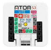
DUH ... Reading ON the Atom S3 Lite, excluding 5V and GND, the other are GPIO1 and GPIO2 (bottom of picture) ...

1711357014849.png

EDIT:
@MrPablo: fair point that i didn't buy the recommended CAN module, but the one recommended cannot be bought anywhere (I only checked Mouser and Digikey, maybe other distributors exist ...).

Maybe on Mouser in a month time !
 
Last edited:
DUH ... Reading ON the Atom S3 Lite, excluding 5V and GND, the other are GPIO1 and GPIO2 (bottom of picture) ...

View attachment 204518

EDIT:
@MrPablo: fair point that i didn't buy the recommended CAN module, but the one recommended cannot be bought anywhere (I only checked Mouser and Digikey, maybe other distributors exist ...).

Maybe on Mouser in a month time !
Yes, I've been looking at getting that base to use with some of my non-S3 atoms, but it looks like AliExpress is the least expensive option for a standalone base.
 
Yes, I've been looking at getting that base to use with some of my non-S3 atoms, but it looks like AliExpress is the least expensive option for a standalone base.
Now with pin 1 & pin 2 it won't work at all. Cannot even build ...

Relevant part of the configuration yml
YAML:
# +--------------------------------------+
# | ESP32 CAN port pins                  |
# +--------------------------------------+
  # GPIO pins your CAN bus transceiver (TJA1050, TJA1051T or SN65HVD230) is connected to the ESP, note! TX->TX and RX->RX.
  # Old: Atom S3 Lite + CAN Hat -> Refer to https://docs.m5stack.com/en/atom/atom_can -> CAN_TX = GPIO22, CAN_RX = GPIO19
  # New: Atom S3 Lite + CAN Hat -> Refer to https://docs.m5stack.com/en/unit/can -> RXD = GPIO16 , TXD = GPIO17
  # Final: Refer to Sleeper85 GitHub Repository -> https://github.com/Sleeper85/esphome-jk-bms-can/blob/main/config/config_atom-s3-lit>
  #can_tx_pin: GPIO17 # DIRECT According to https://docs.m5stack.com/en/unit/can
  #can_rx_pin: GPIO16 # DIRECT According to https://docs.m5stack.com/en/unit/can
  #can_tx_pin: GPIO16 # REVERSED According to https://docs.m5stack.com/en/unit/can
  #can_rx_pin: GPIO17 # REVERSED According to https://docs.m5stack.com/en/unit/can
  #can_tx_pin: GPIO5 # DIRECT According to https://github.com/Sleeper85/esphome-jk-bms-can/blob/main/config/config_atom-s3-lite-esp32->
  #can_rx_pin: GPIO6 # DIRECT According to https://github.com/Sleeper85/esphome-jk-bms-can/blob/main/config/config_atom-s3-lite-esp32->
  #can_tx_pin: GPIO6 # REVERSED According to https://github.com/Sleeper85/esphome-jk-bms-can/blob/main/config/config_atom-s3-lite-esp3>
  #can_rx_pin: GPIO5 # REVERSED According to https://github.com/Sleeper85/esphome-jk-bms-can/blob/main/config/config_atom-s3-lite-esp3>
  can_tx_pin: GPIO1 # According to what is displayed on the face of the ATOM S3 Lite https://shop.m5stack.com/products/atoms3-lite-esp>
  can_rx_pin: GPIO2 # According to what is displayed on the face of the ATOM S3 Lite https://shop.m5stack.com/products/atoms3-lite-esp>

Code:
INFO ESPHome 2024.3.0
INFO Reading configuration esp32-ble-1.17.4.yaml...
INFO Updating https://github.com/syssi/esphome-jk-bms.git@main
INFO Detected timezone 'Europe/Copenhagen'
Failed config

output.gpio: [source esp32-ble-1.17.4.yaml:274]
 
  Pin 2 is used in multiple places.
  platform: gpio
  pin:
    number: 2
    mode:
      output: True
      input: False
      open_drain: False
      pullup: False
      pulldown: False
    inverted: False
    ignore_strapping_warning: False
    drive_strength: 20.0
  id: led
  inverted: True
canbus.esp32_can: [source esp32-ble-1.17.4.yaml:1010]
 
  Pin 2 is used in multiple places.
  platform: esp32_can
  tx_pin: 1
  rx_pin: 2
  can_id: 4
  bit_rate: 500KBPS
  on_frame:
    - can_id: 773
      then:
        - light.toggle:
            id: blue_led
        - lambda: !lambda |-
            id(can_ack_counter) = 0;                              // Reset ACK counter
            id(can_bus_status).publish_state(true);               // Set CANBUS Status to ON
            ESP_LOGI("main", "received can id: 0x305 ACK");
      can_id_mask: 536870911
      use_extended_id: False
  use_extended_id: False
 
Reading this:

https://shop.m5stack.com/products/atoms3-lite-esp32s3-dev-kit -> AtomS3 Lite ESP32S3 Dev Kit (SKU: C124)
https://shop.m5stack.com/products/atomic-canbus-base-ca-is3050g -> ATOMIC CANBus Base (CA-IS3050G) SKU: A103

But A103 is NOT stated as isolated and cannot be sourced from Digikey or Mouser (not in stock). How would I even be supposed to connect the A103 to the Atom S3 Lite ???

EDIT: that's why I went with U805 instead (avalability, and it connects using that 4 pin compact header): https://shop.m5stack.com/products/canbus-unitca-is3050g
also reading ON the CAN BUS ISOLATION ;-)
1711357916632.png
 
Now with pin 1 & pin 2 it won't work at all. Cannot even build ...

Relevant part of the configuration yml
YAML:
# +--------------------------------------+
# | ESP32 CAN port pins                  |
# +--------------------------------------+
  # GPIO pins your CAN bus transceiver (TJA1050, TJA1051T or SN65HVD230) is connected to the ESP, note! TX->TX and RX->RX.
  # Old: Atom S3 Lite + CAN Hat -> Refer to https://docs.m5stack.com/en/atom/atom_can -> CAN_TX = GPIO22, CAN_RX = GPIO19
  # New: Atom S3 Lite + CAN Hat -> Refer to https://docs.m5stack.com/en/unit/can -> RXD = GPIO16 , TXD = GPIO17
  # Final: Refer to Sleeper85 GitHub Repository -> https://github.com/Sleeper85/esphome-jk-bms-can/blob/main/config/config_atom-s3-lit>
  #can_tx_pin: GPIO17 # DIRECT According to https://docs.m5stack.com/en/unit/can
  #can_rx_pin: GPIO16 # DIRECT According to https://docs.m5stack.com/en/unit/can
  #can_tx_pin: GPIO16 # REVERSED According to https://docs.m5stack.com/en/unit/can
  #can_rx_pin: GPIO17 # REVERSED According to https://docs.m5stack.com/en/unit/can
  #can_tx_pin: GPIO5 # DIRECT According to https://github.com/Sleeper85/esphome-jk-bms-can/blob/main/config/config_atom-s3-lite-esp32->
  #can_rx_pin: GPIO6 # DIRECT According to https://github.com/Sleeper85/esphome-jk-bms-can/blob/main/config/config_atom-s3-lite-esp32->
  #can_tx_pin: GPIO6 # REVERSED According to https://github.com/Sleeper85/esphome-jk-bms-can/blob/main/config/config_atom-s3-lite-esp3>
  #can_rx_pin: GPIO5 # REVERSED According to https://github.com/Sleeper85/esphome-jk-bms-can/blob/main/config/config_atom-s3-lite-esp3>
  can_tx_pin: GPIO1 # According to what is displayed on the face of the ATOM S3 Lite https://shop.m5stack.com/products/atoms3-lite-esp>
  can_rx_pin: GPIO2 # According to what is displayed on the face of the ATOM S3 Lite https://shop.m5stack.com/products/atoms3-lite-esp>

Code:
INFO ESPHome 2024.3.0
INFO Reading configuration esp32-ble-1.17.4.yaml...
INFO Updating https://github.com/syssi/esphome-jk-bms.git@main
INFO Detected timezone 'Europe/Copenhagen'
Failed config

output.gpio: [source esp32-ble-1.17.4.yaml:274]
 
  Pin 2 is used in multiple places.
  platform: gpio
  pin:
    number: 2
    mode:
      output: True
      input: False
      open_drain: False
      pullup: False
      pulldown: False
    inverted: False
    ignore_strapping_warning: False
    drive_strength: 20.0
  id: led
  inverted: True
canbus.esp32_can: [source esp32-ble-1.17.4.yaml:1010]
 
  Pin 2 is used in multiple places.
  platform: esp32_can
  tx_pin: 1
  rx_pin: 2
  can_id: 4
  bit_rate: 500KBPS
  on_frame:
    - can_id: 773
      then:
        - light.toggle:
            id: blue_led
        - lambda: !lambda |-
            id(can_ack_counter) = 0;                              // Reset ACK counter
            id(can_bus_status).publish_state(true);               // Set CANBUS Status to ON
            ESP_LOGI("main", "received can id: 0x305 ACK");
      can_id_mask: 536870911
      use_extended_id: False
  use_extended_id: False
Can you attach your YAML (I'm having some sort of flashback here) and we can review?
 

diy solar

diy solar
Back
Top