diy solar

diy solar

JK-BMS-CAN with new Cut-Off Charging Logic (open-source)

Can you attach your YAML (I'm having some sort of flashback here) and we can review?
Sure.

Here it is.

Also the "secrets.yaml" file (redacted for the "real" secrets, other parameters were left "as it is"):
YAML:
host_name: jk-bms-bat02

wifi_ssid: MY_WIFI_SSID
wifi_password: MY_WIFI_PASSWORD
wifi_domain: .solar.MYDOMAIN.TLD

jk_mac_address: C8:47:8C:E5:98:96
jk_protocol: JK02_24S

project_name: Sleeper85.esphome-jk-bms-can
project_version: 1.17.4

board: esp32-s3-devkitc-1

ota_password: MY_OTA_PASSWORD

web_server_username: MY_WEBSERVER_USER
web_server_password: MY_WEBSERVER_PASSWORD

mqtt_host: 172.22.1.1
mqtt_port: 1883
mqtt_username: ""
mqtt_password: ""

Also attached the build script which sets the {{board}} and {{variant}} parameters that couldn't be set as "secret".
 

Attachments

  • esp32-ble-1.17.4.yaml.txt
    89.8 KB · Views: 1
  • build_esphome_jk_bms_can.sh.txt
    2 KB · Views: 0
the conflict is caused due to GPIO2 is assigned to the LED by default
see issue and suggestion here: https://github.com/Sleeper85/esphome-jk-bms-can/issues/27

Need to assign another pin to the LED (for example GPIO35)
Alright ... Not even sure what the LED does, nothing lights up in my case when I toggled it on the webserver previously ...

I set this according to your link (thanks !)
YAML:
output:
  - platform: gpio
    pin: 35
    id: led
    inverted: true

I don't think it will do anything in my case, but it wasn't doing anything before either.

@MrPablo: I am building now with this change (in this current post) implemented ... That is NOT reflected in the files I uploaded a few minutes ago !
 
EDIT. maybe GPIO35 is not a great idea on the Atom S3 Lite ...

Code:
WARNING GPIO35 is used by the PSRAM interface on ESP32-S3R8 / ESP32-S3R8V and should be avoided on these models

Maybe GPIO38 which is exposed on the Atom S3 Lite instead ?

Messing with PSRAM seems a bad idea after all ...
 
OK I think I need to swap GPIO1 and GPIO2 ... Nothing is happening even though the ESP32 is sending some CAN messages ...
 
Alright ... Not even sure what the LED does, nothing lights up in my case when I toggled it on the webserver previously ...
for the esp32doit-devkit-v1 the blue onboard LED will state the CAN bus activity and this LED is connected to GPIO2

The Atom S3 does not have any configurable onboard LED, and the lite does have one but it is an RGB LED and not yet implemented (but will be on the new release)
 
for the esp32doit-devkit-v1 the blue onboard LED will state the CAN bus activity and this LED is connected to GPIO2

The Atom S3 does not have any configurable onboard LED, and the lite does have one but it is an RGB LED and not yet implemented (but will be on the new release)
Alright ... Now cansniffer is dumping something. This is promising (FINALLY !)

Code:
63|ms | ID  | data ...     < can0 # l=20 h=100 t=500 slots=6 >
99999 | 351 | 27 02 42 02 08 07 D0 01 '.B.....
99999 | 355 | 33 00 63 00 EC 13 96 05 3.c.....
99999 | 356 | FD 14 ED 01 B6 00 2C 00 ......,.
99999 | 359 | 00 00 00 00 03 00 00 00 ........
99999 | 35E | 50 59 4C 4F 4E 20 20 20 PYLON
99999 | 379 | 18 01 00 00 00 00 00 00 ........

Now moving back to inverter and 10m cable ...

EDIT 1:

Maybe I'll need to swap Pin 4 & Pin 5 on the RJ45 again .. Let's see.

For those wondering this is my configuration now for CAN pinout:
YAML:
# +--------------------------------------+
# | ESP32 CAN port pins                  |
# +--------------------------------------+
  # GPIO pins your CAN bus transceiver (TJA1050, TJA1051T or SN65HVD230) is connected to the ESP, note! TX->TX and RX->RX.
  # Old: Atom S3 Lite + CAN Hat -> Refer to https://docs.m5stack.com/en/atom/atom_can -> CAN_TX = GPIO22, CAN_RX = GPIO19
  # New: Atom S3 Lite + CAN Hat -> Refer to https://docs.m5stack.com/en/unit/can -> RXD = GPIO16 , TXD = GPIO17
  # Final: Refer to Sleeper85 GitHub Repository -> https://github.com/Sleeper85/esphome-jk-bms-can/blob/main/config/config_atom-s3-lit>
  #can_tx_pin: GPIO17 # DIRECT According to https://docs.m5stack.com/en/unit/can
  #can_rx_pin: GPIO16 # DIRECT According to https://docs.m5stack.com/en/unit/can
  #can_tx_pin: GPIO16 # REVERSED According to https://docs.m5stack.com/en/unit/can
  #can_rx_pin: GPIO17 # REVERSED According to https://docs.m5stack.com/en/unit/can
  #can_tx_pin: GPIO5 # DIRECT According to https://github.com/Sleeper85/esphome-jk-bms-can/blob/main/config/config_atom-s3-lite-esp32->
  #can_rx_pin: GPIO6 # DIRECT According to https://github.com/Sleeper85/esphome-jk-bms-can/blob/main/config/config_atom-s3-lite-esp32->
  #can_tx_pin: GPIO6 # REVERSED According to https://github.com/Sleeper85/esphome-jk-bms-can/blob/main/config/config_atom-s3-lite-esp3>
  #can_rx_pin: GPIO5 # REVERSED According to https://github.com/Sleeper85/esphome-jk-bms-can/blob/main/config/config_atom-s3-lite-esp3>
  #can_tx_pin: GPIO1 # First Attempt - cansniffer doesn't dump anything - According to what is displayed on the face of the ATOM S3 Li>
  #can_rx_pin: GPIO2 # First Attempt - cansniffer doesn't dump anything - According to what is displayed on the face of the ATOM S3 Li>
  can_tx_pin: GPIO2 # Second Attempt - cansniffer is successfully dumping some CAN frames - According to what is displayed on the face of the ATOM S3 Lite https://shop.m5stack.com/product>
  can_rx_pin: GPIO1 # Second Attempt - cansniffer is successfully dumping some CAN frames - According to what is displayed on the face of the ATOM S3 Lite https://shop.m5stack.com/product>

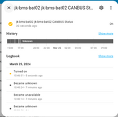
EDIT 2: Reversed Pin 4 & Pin 5. Now CANbus is reporting status OK.
1711360056705.png

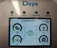
Inverter is reporting "Normal" now.
1711360139185.png

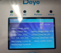
And finally some lithium information on the inverter as well
1711360205365.png

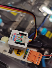
And some information in case somebody else is facing the same issue with this module ...
1711360296980.png

1711360316772.png

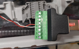
Note that the RJ45 pin/locking tab is sticking "UP".

CAN_H -> Red
CAN_L -> White

Not sure if these are the correct colors but this is what I have and works now. FINALLY.

Stupid me using the wrong pinout. But IMHO this should be included in the documentation @MrPablo ;) .

EDIT 2: This is the RJ45 Breakout adapter I am using, in case other people are interested. It's not that expensive IMHO
 
Last edited:
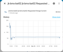
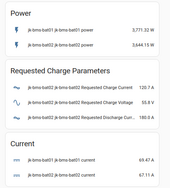
Maybe I made the charge control WAY to aggressive
1711360648904.png

Keep in mind that the 180A (or around 60A now) are for 2 batteries ....
 
Something is very wrong.
I have 2 entities in MQTT and I disabled what I believe was the old one (which had some activity, but is the wrong/old ESP32 board, NOT the ESP32s3):
1711361448078.png

Item number 2 is disabled.

1711361489337.png

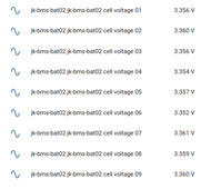
Now only 9 cell are being reported.

What is going on ?

Do I really need 2 MQTT devices for the same physical device ?

EDIT 1: Might be something temporary after i disabled item number 2. Re-enabled and Re-disabled item number 2. Now all 16 cells are back in frontend. Weird ...
 
DUH ... Reading ON the Atom S3 Lite, excluding 5V and GND, the other are GPIO1 and GPIO2 (bottom of picture) ...

View attachment 204518

EDIT:
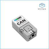
@MrPablo: fair point that i didn't buy the recommended CAN module, but the one recommended cannot be bought anywhere (I only checked Mouser and Digikey, maybe other distributors exist ...).

Maybe on Mouser in a month time !
Got mine from here:
 
Stupid me using the wrong pinout. But IMHO this should be included in the documentation @MrPablo ;) .
Like I said, feel free to submit a pull request.
I don't think we can preemptively document pinouts for hardware that we're not using internally and that isn't tested by us.
It'll become a burdensome task rather quickly.
 
The way I see it,
it takes at most one trial and error swap to get the BMS-UART pins correct.
Whether the wires are physically swapped at the BMS side, or the s/w definition side. Anyone of the two, but never both at once.

The same goes for trial and error swap to get the UART-CAN pins.
Wires swap possibility is at the ESP to CAN transceiver UART side or again the s/w definition side. Anyone of the two, never both at once.

Regarding the inverter CANH/L side, there is only one physical wire swap possibility at the inverter side.
 
Last edited:
Like I said, feel free to submit a pull request.
I don't think we can preemptively document pinouts for hardware that we're not using internally and that isn't tested by us.
It'll become a burdensome task rather quickly.
Again, it's a valid point :).

But like I said, I didn't know where to buy the recommended adapter and didn't want to wait 1 month or so ...
Plus I cannot figure out how it would connect to the Atom S3 Lite in the first place.

Do you have some schematic / photos for that ?
 
The way I see it,
it takes at most one trial and error swap to get the BMS-UART pins correct.
Whether the wires are physically swapped at the BMS side, or the s/w definition side. Anyone of the two, but never both at once.

The same goes for trial and error swap to get the UART-CAN pins.
Wires swap possibility is at the ESP to CAN transceiver UART side or again the s/w definition side. Anyone of the two, never both at once.

Regarding the inverter CANH/L side, there is only one physical swap possibility at the inverter side.
Regarding the inverter CANH/L side, there is only one physical swap possibility at the ESP32 side :) . You cannot tinker with the inverter PCB (or at least I wouldn't recommend doing so).
 
Again, it's a valid point :).

But like I said, I didn't know where to buy the recommended adapter and didn't want to wait 1 month or so ...
Plus I cannot figure out how it would connect to the Atom S3 Lite in the first place.

Do you have some schematic / photos for that ?
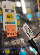
It's quite a nice unit, the Atom has sockets on the underneath that mate up with the pins on the adaptor. It essentially just plugs in.
1711362810913.png
I've just spotted that it's now marked as EOL on the M5stack site - not great news.
 
Something is very wrong.
I have 2 entities in MQTT and I disabled what I believe was the old one (which had some activity, but is the wrong/old ESP32 board, NOT the ESP32s3):
View attachment 204532

Item number 2 is disabled.

View attachment 204533

Now only 9 cell are being reported.

What is going on ?

Do I really need 2 MQTT devices for the same physical device ?

EDIT 1: Might be something temporary after i disabled item number 2. Re-enabled and Re-disabled item number 2. Now all 16 cells are back in frontend. Weird ...
Once you changed the details for the MQTT of the build firmware, you need o clean MQTT, in some cases you also need to remove the device under MQTT add-on and/or the last step (may not need but can be last resource) is to restart MQTT server.
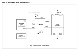
Regarding your Can bus problem. Please check to see the impedance of the entire wire! See the test case for the TJA1050. Can refer to this as well, page 21: https://www.nxp.com/docs/en/application-note/AN00020.pdf
1711363122780.png
 
Last edited:
It's quite a nice unit, the Atom has sockets on the underneath that mate up with the pins on the adaptor. It essentially just plugs in.
View attachment 204543
Alright ... But the A103 SKU for that I cannot find anywhere. Maybe in stock by Mouser in 1 month ...

The closest in look is this one, but likely ESP32 + CAN module "in one unit" (everything included)

Then you have the orange terminal block connector on the upper side of your picture ?

EDIT: Aliexpress to the rescue maybe

Thanks for the link to the store @chaosnature
 
Once you changed the details for the MQTT of the build firmware, you need o clean MQTT, in some cases you also need to remove the device under MQTT add-on and/or the last step (may not need but can be last resource) is to restart MQTT server.
Regarding your Can bus problem. Please check to see the impedance of the entire wire! See the test case for the TJA1050. Can refer to this as well, page 21: https://www.nxp.com/docs/en/application-note/AN00020.pdf
View attachment 204547
It is working correctly now. WITHOUT termination resistor even ...
 
It is working correctly now. WITHOUT termination resistor even ...
Often when the run is short and there are no more than 2 nodes on the CANbus then you can get away without a termination resistor at both ends.
The spec calls for it though, and it will likely reduce errors.
If / when there's a multiBMS solution over CANbus, it will become more critical.
 
There is a bit of a difference between requested / actual current though.
Keep in mind that I am ONLY controlling batter 02. Battery 01 will just get whatever the inverter deliver minus what is taken by battery 02.

120A requested , 140A delivered ... Uhm ...

1711363593954.png

And looking at the Charge control spreadsheet it should go up to 144 A which is much closer to the delivered value.
 
Often when the run is short and there are no more than 2 nodes on the CANbus then you can get away without a termination resistor at both ends.
The spec calls for it though, and it will likely reduce errors.
If / when there's a multiBMS solution over CANbus, it will become more critical.
So should I just put it back ?
 
There is a bit of a difference between requested / actual current though.
Keep in mind that I am ONLY controlling batter 02. Battery 01 will just get whatever the inverter deliver minus what is taken by battery 02.

120A requested , 140A delivered ... Uhm ...

View attachment 204549

And looking at the Charge control spreadsheet it should go up to 144 A which is much closer to the delivered value.
Interesting, that suggests that either the inverter is not respecting the CCL, or there's a calibration issue on your BMSs, but that would be a hell of a difference...

As for the resistor, it's up to you.
 
Interesting, that suggests that either the inverter is not respecting the CCL, or there's a calibration issue on your BMSs, but that would be a hell of a difference...

As for the resistor, it's up to you.
What do you mean "Interesting" :ROFLMAO:?

With 800 W / m2 measured by my weather station (it has never been that high !) for sure it can produce 20 kW or even more :ROFLMAO:

So somewhat it is respecting ...

EDIT 1:
Let me try to increase the current limit on the inverter and see if that wasn't the limiting factor

EDIT 2:
Re-added resistor :ROFLMAO:
1711364276646.png

EDIT 3: I'm not fully sure how it works with 3 inverters in parallel, maybe the given battery current reference is delayed when communicated to the slave inverters? Plus possibly 3x measurement errors on 3 inverter ?

EDIT4: and of course now that i'd like to test Clouds came back and sitting at around 150 W/m2.
 
Last edited:
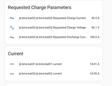
I tuned the max charging current to 45A using the slider (i.e. 45A for both batteries) for a quick test.

Current dropped accordingly so it IS working. Not ultra precise, but good enough
1711365101097.png

EDIT: I also probably made the current control WAY too aggressive. But since OTA didn't work last time, I am not so sure about reflashing ...
 

diy solar

diy solar
Back
Top