diy solar

diy solar

JK bms is blowing up rs 485 converter

piper18o

New Member
Joined
Mar 20, 2023
Messages
12
Location
Kansas
I have 6 eve 48 volt lifepo4 batteries with 16 cells per battery. I have a jk bms on each one. I am using solar assistant. A while back, battery number 4 quit monitoring. I can still monitor it with the jk ap, but I can't see it on my solar assistant software. After a series of trial and error, I have discovered that the number 4 bms that I can't monitor is killing every rs 485 converter I put on. Why would it do this? I went through about 3 new converters before I realized what was happening. I figured it out when I took a working converter from bms and battery number 1 and put it on the non reporting bms, (#4). When it didn't work, I put it back on number 1 bms that was working and it no longer reported data. I then replaced the converter, and number 1 reported again. So why is the BMS on battery #4 killing the converter?
 

Attachments

  • rs485 converter.jpeg
    rs485 converter.jpeg
    40.3 KB · Views: 0
Last edited:
RS485 communication voltage is -7 to +12V and the transceiver IC would be powered by 3.3 or 5V. Most likely there is some high voltage leakage from the 48V battery damaging the electronics in the adapter.
 
There is a limit on voltage between the data line twisted pair and any reference ground.

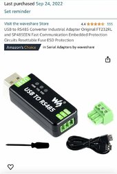
There is basically three grades of quality for USB to RS485 converters.

1) lowest, shares USB +5v to power RS485 converter chip. No ESD protection.

2) medium - shares USB +5v to power RS485, has ESD protection on RS485 balanced data pair to ground.

3) high - isolated DC to DC converter between USB +5v and +5vdc supply on RS485 chip. Data from USB to serial converter chip to RS485 converter chip has opto or magnetic isolation transformer. RS485 outputs have ESD protection. These converters can take up to several thousand volts of difference between USB and RS485. USB data to RS485 data is very well isolated from any voltage surge on either end of line.

Since USB end is likely grounded, don't ground BMS end, just use two data pair wires. If you use the high grade isolated converter you can also ground the RS485 end to BMS. The RS485 end still has the 7-12v limit between its grounded end and data pair wires. It just has its own ground reference due to the isolation.

The third grade is often referred to as 'industrial' grade.

Lowest grade, couple of dollars

Highest grade, 20-30 dollars.
 
Last edited:
I have 6 eve 48 volt lifepo4 batteries with 16 cells per battery. I have a jk bms on each one. I am using solar assistant. A while back, battery number 4 quit monitoring. I can still monitor it with the jk ap, but I can't see it on my solar assistant software. After a series of trial and error, I have discovered that the number 4 bms that I can't monitor is killing every rs 485 adapter I put on. Why would it do this? I went through about 3 new adapters before I realized what was happening. I figured it out when I took a working adapter from bms and battery number 1 and put it on the non reporting bms, (#4). When it didn't work, I put it back on number 1 bms that was working and it no longer reported data. I then replaced the adapter, and number 1 reported again. So why is the BMS on attery #4 killing the adapter?
What brand(s) blew up?
 
There is a limit on voltage between the data line twisted pair and any reference ground.

There is basically three grades of quality for USB to RS485 converters.

1) lowest, shares USB +5v to power RS485 converter chip. No ESD protection.

2) medium - shares USB +5v to power RS485, has ESD protection on RS485 balanced data pair to ground.

3) high - isolated DC to DC converter between USB +5v and +5vdc supply on RS485 chip. Data from USB to serial converter chip to RS485 converter chip has opto or magnetic isolation transformer. RS485 outputs have ESD protection. These converters can take up to several thousand volts of difference between USB and RS485. USB data to RS485 data is very well isolated from any voltage surge on either end of line.

Since USB end is likely grounded, don't ground BMS end, just use two data pair wires. If you use the high grade isolated converter you can also ground the RS485 end to BMS. The RS485 end still has the 7-12v limit between its grounded end and data pair wires. It just has its own ground reference due to the isolation.

The third grade is often referred to as 'industrial' grade.

Lowest grade, couple of dollars

Highest grade, 20-30 dollars.
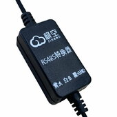
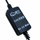
Sorry, I meant this converter that goes between the bms and the adapter. That is what goes bad when I hook it up to bms #4
 

Attachments

  • rs485 converter.jpeg
    rs485 converter.jpeg
    40.3 KB · Views: 1
Last edited:
Sorry, I meant this converter that goes between the bms and the adapter. That is what goes bad when I hook it up to bms #4
I'm pretty sure JK make two versions one for 12-24v and one for 48v batteries, do you have the right one from your supplier?
 
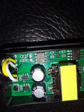
These JK BMS adapters are basically a DC-DC converter, a isolator (CS817x22) and MAX485 type clone IC (3Peak TP8485E) .
Per this pic, the TTL-RS485 path is at the top part of the PCB (where the black, yellow and white wires leave the PCB).
20240327_095240.jpg

It could be that the BMS is frying adapters by putting the high (battery) voltage on the signal path.
Unfortunately it's probably going to be a case of replacing that BMS.

One way to quickly check, is to get a multimeter and check both the Tx and Rx from the BMS, with respect to ground and each other.
If any exceed ~5V, the BMS should probably be replaced as they are a nightmare to fault find and repair.
 
Last edited:
Back
Top