diy solar

diy solar

JK bms mounting position

Skypower

Solar Wizard
Joined
Aug 23, 2021
Messages
2,026
I’m planning on mounting JK 200amp versions on the end of a 16S wooden battery boxes. For ease of connection, supplied balance wire length and seeing status light, I’m orienting it connector end up (FET end down). The bms would be spaced off the box about 3/16” by the use of four 1” square 3M cable tie mounts so there should be plenty of room for convection cooling all around. A dab of Shoegoop on the cable ties to keep it from slipping down over time. There’s an identical battery box/bms and they will be placed so the bms’s are back to back (bump to bump) with about 1 1/2” spacing between them. The batteries reside under a workbench where the batteries are protected and kept away from dirt and large dust but are easily accessible by a lift away bench top. The area above the battery banks/bms’s are protected but there is a 4” clearance above them that allows ambient air. All wood has been soaked in fire retardant. The inverters have an absolute maximum continuous total limit of 300 amps (150 per bms) yet the Daly that’s going to be replaced has only ever seen half that total load. So normal high daily, non surge, continuous long load (15 minutes +) is going to be about 50 amps per bms. I’ll be setting each current overload at 175 amps with a short time delay and I have a 250amp fast T class fuse on each as well. Yes the FET end up would probably keep much of the heat away from the fine board components and light setting dust at the connector end (probably just put a Kapton tap over the end) but it’s going to be a lot more work to turn it around. I don’t know how much warmth the JK’s generate, the 300A Daly’s heat was imperceptible and the it’s fan came on exactly one time during the heat wave with the hvac on.
Just go with the plan JK connector up? Comments?
 
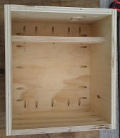
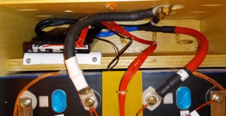
Image below is how I built my Battery Boxes. Between the Batt Terminal Face and the separator, the space is 3". The JKBMS is installed in the space with connections, LED facing up. The BMS is attached to a plastic L Bracket using small screws and offset about 1/4" from the separator board. I have checked them regularly for heat (just in case & under heavy load) and the BMS does warm up a tad, it's not enough to worry about at all. There have been no "Hot" spots at all and the MOS Temp is reasonable.

NOTE: The screw holes on the back of the BMS are tiny & shallow, I used screws from a dismantled PC, in fact the screws used to attach hard disks, not casing screws.

Box Assembled (A).jpg 1665335845509.png
 
Excellent info, thanks!
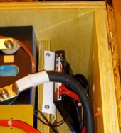
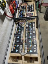
I’ve got what appears to be an opening but it’s where the compression spring is so I have to think outside the box. Right now it’s opening in 2P 16S but I don’t trust the Daly so the 2P jumpers are going away. There’s actually four 8 cell modules so it’s easy to move to a new home. The modules will be moved apart at the center 07A98324-3E83-4C88-99D7-C0CD869F2E06.jpeg1B7D6B98-3E7F-4FCC-BFA2-47DB3FA7942A.jpeg(under the cross bar) for the bms’s to make two groups of 16 cells. The new center feed point will reduce the total 2/0 cable length by over 8’. I’m so glad I didn’t take the time to make neat the balance leads because of the evolutions of Heltec to Neey balancers to new bms’s. But I’ll take the time this go.

How did you connect the two 7awg bms cables to the 2/0? I was thinking of just using a #4 lug and bolt it to 2/0 lug then double heat shrink it. A 2/0 butt connectors quading over wire or progressive lug barrels doesn’t seem appealing.
 
Last edited:
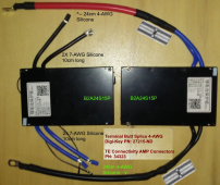
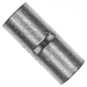
The two 7AWG coming out = 4AWG combined. I used Ultra-fine stand Silicone wire for the extensions. The "Butt Connector) has a dimple in the centre to get a good "mid-point" stop and allowed me to double crimp each side with my hydraulic crimper. THIS IS JUST FOR THE BMS ! I wanted to get Blue & Black silicone wire but Blue was out of stock. Getting both 7AWG into the 4AWG hole is really difficult ! It generated a bit of Blue Air when I was doing up all the BMS', patience & care is required.

The 2/0 you see there is the (+) with a Selterm 2/0 awg 5/16 hole (Cell End) and the other end is a Selterm 2/0 awg with 3/8 hole for the bulkhead connector. Why 2/0 ? I already had a handful made up that I used when I had the Chargery BMS' so recycled them.

A different view
1665348116706.png

1665349573493.png

1665348568291.png

https://www.digikey.ca/en/products/detail/te-connectivity-amp-connectors/34323/292935
 
Last edited:
Yeah it’s tough to get them both 7’s into a #4 lol. The calculator said it would fit but I didn’t believe it till I did it. Found an easy way using fine mechanics wire or stripped hd garbage bag wire ties. First strip both wires to the appropriate length then twist tie or tie strap the rubber parts together even. Now tightly do a couple of wraps and twist tie the strands together. Now slide the wrap close to the end. The lug should easily start onto the wire and push the wrap back or un rap now or before you push the lug home. No more blue air or at least this chore.
 
The real problem was that the BUTT Connector does not have flared ends, if it did, then it would not have been an issue. By the 3rd BMS I got the hang of it.
 
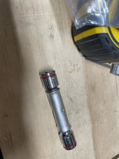
Yeah been there done that. I got to be careful so I don’t blow a fuse so I ponder it over a cup of coffee. Hammer or vice?A41C0D9D-C378-4328-9C2F-59DE26BEB78B.jpeg
 
My mantra, cheat the job. ? Kobalt sockets work great for opening up that lug stud size to the next size too without removing material. Like a 5/16 to a 3/8”. Hammer, socket, two 3/8” washers for backup, 7/16 nut for spacing and a hard surface. Work both sides with only two blows to keep it flat. Try to drill a lug out without a vice and I’ll make blue air. They always freaking grab.
 
I’m planning on mounting JK 200amp versions on the end of a 16S wooden battery boxes. For ease of connection, supplied balance wire length and seeing status light, I’m orienting it connector end up (FET end down). The bms would be spaced off the box about 3/16” by the use of four 1” square 3M cable tie mounts so there should be plenty of room for convection cooling all around.
I am just reviewing option for mounting my first JK BMS 200 amp 16S version. Gotta say your ideas make sense to me, and match my thoughts about convection cooling. After reading your post here, I will make sure my BMS status light is also facing up. :+)
 
I use the 3mm threaded bottom holes on back of BMS to attach to a 90 degree bracket. Connectors and LED up. I use either two 6ga X 1/4” lugs on the blue wires or one 2ga butt splice if extension is needed - easier to get those hairy cables inserted in a 2ga. Amazon sells all lugs/butt splices.
 
I use the 3mm threaded bottom holes on back of BMS to attach to a 90 degree bracket. Connectors and LED up. I use either two 6ga X 1/4” lugs on the blue wires or one 2ga butt splice if extension is needed - easier to get those hairy cables inserted in a 2ga. Amazon sells all lugs/butt splices.
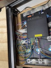
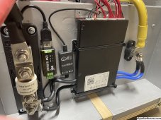
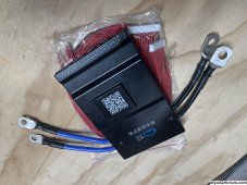
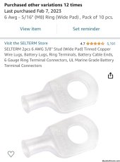
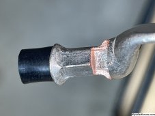
Well they have been up and running for a while and have been performing flawlessly (after learning about setting SOC) I have three JK’s and they are running strong and cool ( a 4th spare, prepped, tested with settings). I went with the #6 wide lugs. 3/8” for the fuses side and 5/16” for the terminal post. This allows extra flexibility in lug position and placement, not as locked in shape as two crimped together. The dies used to crimp a 7AWG in a 6AWG lug are a combination 6 and 8. The lugs corners of the dies were radius as to not pinch off or narrow the lug’s barrel cross section. The lugs were crimped in a position where the flat faces are oriented towards each other on each side of the bms. I used four zip tie mounts to hold and stand off the bms. The mounts are 3M with the adhesive that was helpful to position them while I used two small screws in each to guarantee attachment. I mounted one picture, bms back out to reduce the cable run by over a foot since this battery is on rollers on the floor beneath the two on the shelf. This keeps the cable run length very similar between batteries. By putting my fuse on the negative I reduce my junctions by one for my situation. The positive goes right to the battery.
IMG_0956.jpegIMG_0954.jpegIMG_0957.jpegIMG_0958.jpegIMG_0921.jpeg
 
Last edited:
The two 7AWG coming out = 4AWG combined. I used Ultra-fine stand Silicone wire for the extensions. The "Butt Connector) has a dimple in the centre to get a good "mid-point" stop and allowed me to double crimp each side with my hydraulic crimper. THIS IS JUST FOR THE BMS ! I wanted to get Blue & Black silicone wire but Blue was out of stock. Getting both 7AWG into the 4AWG hole is really difficult ! It generated a bit of Blue Air when I was doing up all the BMS', patience & care is required.

The 2/0 you see there is the (+) with a Selterm 2/0 awg 5/16 hole (Cell End) and the other end is a Selterm 2/0 awg with 3/8 hole for the bulkhead connector. Why 2/0 ? I already had a handful made up that I used when I had the Chargery BMS' so recycled them.

A different view
View attachment 115697

View attachment 115700

View attachment 115698

https://www.digikey.ca/en/products/detail/te-connectivity-amp-connectors/34323/292935
Hi Steve, just had to extend my cable almost the exact same way. Wondering what you used for heat shrink since the wire is coated with 200°C insulation. Doesn't seem to be many options close to home in the north. Best I can find so far is PTFE heatshrink tubing at digikey rated for 260°C but ouch on the price and two weeks out.
 

Attachments

  • hfa.pdf
    434.3 KB · Views: 4
Hi Steve, just had to extend my cable almost the exact same way. Wondering what you used for heat shrink since the wire is coated with 200°C insulation. Doesn't seem to be many options close to home in the north. Best I can find so far is PTFE heatshrink tubing at digikey rated for 260°C but ouch on the price and two weeks out.
I used some Heatshrink with glue "NTC". I bought a bunch of it from an electronics supply house quite a while back. With the silicone wire, even the glue doesn't really stick much, but it does hold onto the butt connector.
 
Excellent info, thanks!
I’ve got what appears to be an opening but it’s where the compression spring is so I have to think outside the box. Right now it’s opening in 2P 16S but I don’t trust the Daly so the 2P jumpers are going away. There’s actually four 8 cell modules so it’s easy to move to a new home. The modules will be moved apart at the center View attachment 115681View attachment 115679(under the cross bar) for the bms’s to make two groups of 16 cells. The new center feed point will reduce the total 2/0 cable length by over 8’. I’m so glad I didn’t take the time to make neat the balance leads because of the evolutions of Heltec to Neey balancers to new bms’s. But I’ll take the time this go.

How did you connect the two 7awg bms cables to the 2/0? I was thinking of just using a #4 lug and bolt it to 2/0 lug then double heat shrink it. A 2/0 butt connectors quading over wire or progressive lug barrels doesn’t seem appealing.

I'm interested how you pressed the connection points on your flexible bus bars.
 
Hi Steve, just had to extend my cable almost the exact same way. Wondering what you used for heat shrink since the wire is coated with 200°C insulation. Doesn't seem to be many options close to home in the north. Best I can find so far is PTFE heatshrink tubing at digikey rated for 260°C but ouch on the price and two weeks out.
I don’t know of anything that would really stick to silicone insulation. If you just want to keep moisture out of the two flutes created by two parallel cables you probably need to use a sealant or dielectric grease in the joint before heat shrinking and let the excess squirt out. Your choices are electrical grade silicone sealant (not the stuff that smells like vinegar) Shoe Goop or NO-OX-ID grease. The silicone probably won’t stick to the insulation, ShoeGoop is too stiff but I’m thinking that the grease will maintain flexible grease plug keeping the moisture out.
 
I'm interested how you pressed the connection points on your flexible bus bars.
I made an embosser. Unfortunately that project was a fail and all those 1” wide flexible straps are residing in a box waiting to be sold as copper scrap. They wouldn’t stay torqued. The solder/copper kept flowing and the connection wasn’t safe. I made cable jumpers for some batteries and bought flexible laminated. It’s laminated from now on.
 
I don’t know of anything that would really stick to silicone insulation. If you just want to keep moisture out of the two flutes created by two parallel cables you probably need to use a sealant or dielectric grease in the joint before heat shrinking and let the excess squirt out. Your choices are electrical grade silicone sealant (not the stuff that smells like vinegar) Shoe Goop or NO-OX-ID grease. The silicone probably won’t stick to the insulation, ShoeGoop is too stiff but I’m thinking that the grease will maintain flexible grease plug keeping the moisture out.
I believe the manufacture gets away with lighter cabling on the BMS due to it's 200°C insulation rating. This rating is what I am concerned about maintaining. Likely just over analyzing and over thinking it but I'll likely get some PTFE heatshrink anyway.
 
Back
Top