diy solar

diy solar

Show me your JK BMS mounting solutions

AlpineJoe

New Member
Joined
Jun 13, 2022
Messages
210
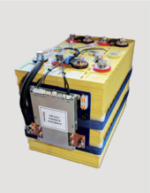
I have a 16 qty bank of CALB 180 cells arranged in a 2p8s configuration and want to add the JK b2a8s20p BMS. JK BMS is aluminum skinned and came with short 7ga silicone insulated wires for connections, 2 in parallel for in and out.
I can’t rest the BMS on top of the cells else short stuff out, and I’m not sure I should be making a 3D box for the BMS for flammability and heat shedding concerns.

I’d like to see how folks have installed their JK BMS with similar pack arrangement as I have. Anyone have photos of their setup?

Thanks
 
Screws and fender washers clamping it to a piece of wood that just layed on top of the batteries. They are not good for mounting.
 
Not using LFP, but we have problems with cyclindrical cell packaging too. I've tried tape, tie-wraps, and blue tape.

Best solution so far is to hang angle brackets off and screw to the battery blocks...I've also used 3M double backed tape. My request to JK is to give us some mounting tabs times four.2023-12-21 13.59.08.jpg2023-12-04 14.07.12.jpg

I've also tried blue tape!!!!! JK help us out here!!!!!!!!! We could use longer cables too!!!

2023-12-21 14.02.38.jpg
 
Not using LFP, but we have problems with cyclindrical cell packaging too. I've tried tape, tie-wraps, and blue tape.

Best solution so far is to hang angle brackets off and screw to the battery blocks...I've also used 3M double backed tape. My request to JK is to give us some mounting tabs times four.

I've also tried blue tape!!!!! JK help us out here!!!!!!!!! We could use longer cables too!!!
Looks good!
 
Where do you get those terminals?
I bought from Alibaba supplier - can share the contact if you are interested. These are not cheap, IIRC about $20 a pair - rated at 300A.
They are separated left to right (ie two isolated terminals) so I cut the plastic separation out from between them in the inside-side and installed a short piece of bus bar to connect the two halves.
Please share
 
I have a 16 qty ........
I’d like to see how folks have installed their JK BMS with similar pack arrangement as I have. Anyone have photos of their setup?

Thanks
BMS ist screwed with with distance on to board of plastic. Board ist mounted to cells with adhesive tape. Board plus stack of cells ist held together with two Straps. Used multiple Times without Problems.
 

Attachments

  • Screenshot_20240208-125015.png
    Screenshot_20240208-125015.png
    693.5 KB · Views: 63
Makes it easier for our customers to shorten and then connect the Balancer wires.
I would be concerned with resistance of the connection. While the balance leads do not carry much current, any extra resistance in the circuit could lead to cell readings that are not accurate.
 
do we know the resistance of the Wago's? (I should measure one and see)
if each lead has the same resistance, does it matter?
are the Wago connector's resistance measurably differenct than a ring terminal?
 
do we know the resistance of the Wago's? (I should measure one and see)
if each lead has the same resistance, does it matter?
are the Wago connector's resistance measurably differenct than a ring terminal?
It is the connection, not the Wago that would concern me.

If the connection on the Wago is not perfect (and I've studied how these are constructed) combined with the low voltage of cells at the beginning, example cell 1 which would be 3.2V nominal, may possibly lead to some imbalance or over/under cell voltage during charge/discharge.

The BMS does read cell voltage open circuit (potential), that does help. However I would never consider using a Wago for a critical component.
 
I used a terminal block set to go from my JBD BMS sense leads to a 12 gauge wire with run lug on the cells.

It was also a convenient way to splice in the active balancer that I could switch on as needed. The JBD never had issues in sensing the cell voltages and the cells never got that out of each that it did harm to the total pack. Cell delta stayed <0.010v at 3.5v

This wago is about the same, I just know people love getting spun up about them.
 
It is the connection, not the Wago that would concern me.

If the connection on the Wago is not perfect (and I've studied how these are constructed) combined with the low voltage of cells at the beginning, example cell 1 which would be 3.2V nominal, may possibly lead to some imbalance or over/under cell voltage during charge/discharge.

The BMS does read cell voltage open circuit (potential), that does help. However I would never consider using a Wago for a critical component.
Why are you so negative on WAGOs?
Up till now I have used several duzend of cheep "lousy" spring-connectors from China. Then I switched to the WAGOs because of their superior design. Since then I used more than 200 such WAGO connections with zero problems.
Even more I did a pull-test on the WAGOs with wires, ending up with close to 5 kg!!!
The overall resistance (measured) of a WAGO connection is much less than 1 milliOhm. This is nothing compared to a typical balance wire with 50 milliOhms. It guess it is more likely that a wire gets loose from a crimped ring terminal than from a WAGO. Should do a pull test......
Can you please explain to me, how the 3.2 V may lead to some imbalance on cell number 1?
 
Last edited:
This one isn't JK but gives you the idea.View attachment 190007

I think I’d replace that fuse/buss with standard buss with a hole drilled for the right spacing. With higher loads, it could lead to some imbalance or the balancer working harder than necessary. If that fuse blows, it’ll route some crazy voltage through the balance circuit. I’d get a fuse holder and mount it inside next to the box’s output terminals. Even better if it’s a Blue Sea + T class fast blow. Not sure what that black wire at the fuse is there for. Picking off some 12 volts? That could also cause some problems especially if there’s a lot of drain.
IMG_1270.jpeg
 
Last edited:
Back
Top