Hi
I have a strange problem: I have 2 DIY packs, both 280ah 24V. One uses JBD BMS (xiaoxiang app) and the other one JK BMS B2A8S20P.
The JBD pack is older it was working like 6 months here and I added the JK pack 2 days ago. Both go onto same 24V busbar.
So far all looked good, however this night I run into this problem:
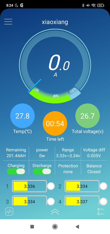
- initially (around 10pm) both packs showed to discharge (power, current different from 0 in their app). I went to sleep then around 6am inverter lost power the JBD pack went down to programmed zero (about 15% SoC 25.5V), however the JK pack was apparently at 26.8V and the JK app showed discharge state off, charge state off - BUT the controls were set to ON (so discharge on, charge on), l mean these in this screen (example picture not mine):
( so the top screen indicators were shown as charge: off, discharge: off, balance: on, DESPITE the knobs under "control" set to ON for charge, discharge).
NO errors logged in system log on the JK BMS. It was also not powered down or so.
Now the question is what is wrong with that? Why would the JK BMS suddenly disable discharge when discharge control is set to ON and log no error?
Any thoughts?
I have a strange problem: I have 2 DIY packs, both 280ah 24V. One uses JBD BMS (xiaoxiang app) and the other one JK BMS B2A8S20P.
The JBD pack is older it was working like 6 months here and I added the JK pack 2 days ago. Both go onto same 24V busbar.
So far all looked good, however this night I run into this problem:
- initially (around 10pm) both packs showed to discharge (power, current different from 0 in their app). I went to sleep then around 6am inverter lost power the JBD pack went down to programmed zero (about 15% SoC 25.5V), however the JK pack was apparently at 26.8V and the JK app showed discharge state off, charge state off - BUT the controls were set to ON (so discharge on, charge on), l mean these in this screen (example picture not mine):
( so the top screen indicators were shown as charge: off, discharge: off, balance: on, DESPITE the knobs under "control" set to ON for charge, discharge).
NO errors logged in system log on the JK BMS. It was also not powered down or so.
Now the question is what is wrong with that? Why would the JK BMS suddenly disable discharge when discharge control is set to ON and log no error?
Any thoughts?