


carpetpaul
New Member
- Joined
- Aug 3, 2022
- Messages
- 22
Forgive me if you've seen my other couple of posts discussing an issue with my JK BMS (both of them) where after correctly cutting off at UVP level (when a small charger is connected during discharge) the BMS turns back on without waiting for the pack to reach UVPR using the charger. I've tried all sorts and cannot get this to work. Tonight I discovered that although both BMS can turn the load off at UVP, when I turn off the discharge setting on the APP, the BMS still allows discharging. I'm confused and wonder if I've done something wrong in the wiring, so here it is :
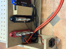
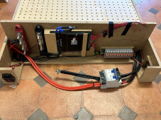
the positive wire from my pack comes from my fuse, straight to a terminal block
the negative wire from my pack goes through the BMS and to the terminal block
to this terminal block, my inverter is directly connected, also is my charger*
does this sound correct ?
* I can turn the charger on and off via the APP, but not the discharge
I'm presuming that BMS should have some kind of diodes or similar that can allow power from the charger in, whilst not allowing power to flow out to the load ? even when I turn the charger off from the APP, I still cannot turn the load / discharge off from the APP

")