diy solar

diy solar

Just want to get a bit of clarification / advice on fuse sizes

WoodyDronesOn

New Member
Joined
Mar 30, 2022
Messages
4
Hi All

Must say thanks to all contributors for the massive amount of information here:

I have looked through a lot of posts on here and also the resources and I now believe that I am closer to an answer to my questions, but still have a few niggling doubts and concerns over the cable sizes provided in the KIT and fuse sizes required.

I brought this kit from Eco-Worthy UK and it arrived in a few days, I have asked their tech department online and got a fast response, I answered a few questions and now nothing from them after I replied in emails, but I may be getting blocked in spam so I have tried again with the online help!

System I brought:

The kit I have varies only in that when I brought it, they supplied it with 4 x 50ah batteries, and this kit is now supplied with 2 x 100ah batteries.

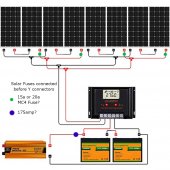
As I am wiring 8 panels together in sets of two to create a 24v system, I believe I need 1 x 20amp MC4 Inline Fuse on each two-panel array The lsc of each panel is 9.89a so I believe that 9.89a x 1.56 gives 15.4284a so round up to 20amp or round down to 15amp as it is close?

I am concerned the cables to the controller are all 12AWG, is this sufficient when the 8 panels are together the combined lsc would be 4 x 9.89a (39.56a), or am I misunderstanding the principles here, I think the 12AWG has a capacity of 30amps?

Likewise, the Battery fuse to the Inverter is a bit unclear and not defined in the instructions and when I look into the information available in the resources section, I get a required fuse rating of 171amps from a 24v 3000w inverter with no allowance for the surge of 6000w, the efficiency is circa 91% is this correct?

Looking at the cables supplied in the kit to connect batteries and the amperage charts they seem to be well undersized, but I should have thought that the kit should be suitable to safely deal with the power from the batteries to the supplied inverter? I don't want a meltdown the moment I switch the inverter on and use it with some high-power loads :)

Any advice would be appreciated as I want to make it as safe as possible.

Many Thanks

Woody
 

Attachments

  • aaaaaaaaaaaaaa.jpg
    aaaaaaaaaaaaaa.jpg
    190.3 KB · Views: 5
With #12 wire each pair should have a separate run to the 60amp PWM controller. Not just the ampacity but the voltage drop. I would soon be looking for an MPPT controller to put at least four panels in series. Can the kit be upgraded?
 
Your 8 panels in a 2S4P arrangement means close to 40A. From the last Y connector to the SCC you need at least 8AWG. It depends on how long that last pair of wires is so you might need 6AWG.

Most MC4 connectors are only good to 30A. I don't know what the supplied Y connectors are rated for. You might not be able to use them.

And a PWM controller is going to give poor results with the 2S setup. I'd replace the PWM controller and get an MPPT solar charge controller. Then you could arrange the panels in 4S2P instead of 2S4P. This will give you much better results and you will only have 20A going to the charge controller from the panel array.
Thanks for that rmaddy, It does look like what is sold as a kit is technically a fire hazard without modification, would this product solve my problem with some additional cable extensions? My solar panels are no more than 3m away from the controller on the other side of a brick wall, so cable length is not a major issue.


This looks like it would provide some protection and also allow the heavier cable to connect to the charge controller.

I will definately look into the MPPT controller, I could probably use the old PWM in the shed as another small project.

I need to look into the cable for the battery to inverter a bit more as they seem to be rated to 125c for the battery connections, but the rest is hard to see labelled on the cable, but I am still worried that it will not cope with full power draw from the 3000w inverter.

I'll update here if Eco-Worthy actually get back to me, about this as it appears dangerous how it is sold and marketed!

Would 4S2P give me a 48v system? instead of the 24v system? Sorry relatively new to all of this even though I have been researching for about 6 months, must be my 50+ year old brain on the way out!

Thanks

Woody
 
Would 4S2P give me a 48v system? instead of the 24v system? Sorry relatively new to all of this even though I have been researching for about 6 months, must be my 50+ year old brain on the way out!

Thanks

Woody
The MPPT will convert the voltage to what is needed for your 24 volt system. No matter if the panels are 40v, 85v, 130v or anything between.
Four in series gives 66 volts and would be converted. Same with eight in series the 132 volts would be converted to the 24 you need. The MPPT will increase amps as it adjusts the voltage down to get every available watt from the panels.

The MPPT controller would need to be compatible with the higher voltage. 100 and 150 volt compatibility is very common.
 
would this product solve my problem with some additional cable extensions?
A 4 string combiner box is a good choice but you probably need 15A breakers. The panels in the kit have an Isc close to 10A so a 10A breaker is too small.

I was just about to talk about the MPPT but I see @time2roll just beat me to it. The only thing I'll add is that with an MPPT SCC you just need to make sure your panel array voltage ends up at least 5V higher than your battery charge voltage. This is easily met by putting those panels in 2S or more.
 
With #12 wire each pair should have a separate run to the 60amp PWM controller. Not just the ampacity but the voltage drop. I would soon be looking for an MPPT controller to put at least four panels in series. Can the kit be upgraded?
Thanks for the reply, that confirmed my fears that the KIT and its wiring diagram would not work together and almost guaranteed to result in a fire, I may be wrong and a bit more research into the cables supplied may be needed, but I now have some options now that I know a bit more. I will look into the MPPT as an upgrade to the kit I can use the PWM in the shed! I am pretty annoyed that potentially there are life safety issues with this KIT and virtually no support responce from them so far. Someone could just install it as shown and have a real problem :(
 
Your 8 panels in a 2S4P arrangement means close to 40A. From the last Y connector to the SCC you need at least 8AWG. It depends on how long that last pair of
A 4 string combiner box is a good choice but you probably need 15A breakers. The panels in the kit have an Isc close to 10A so a 10A breaker is too small.

I was just about to talk about the MPPT but I see @time2roll just beat me to it. The only thing I'll add is that with an MPPT SCC you just need to make sure your panel array voltage ends up at least 5V higher than your battery charge voltage. This is easily met by putting those panels in 2S or more.

wires is so you might need 6AWG.

Most MC4 connectors are only good to 30A. I don't know what the supplied Y connectors are rated for. You might not be able to use them.

And a PWM controller is going to give poor results with the 2S setup. I'd replace the PWM controller and get an MPPT solar charge controller. Then you could arrange the panels in 4S2P instead of 2S4P. This will give you much better results and you will only have 20A going to the charge controller from the panel array.
Thanks, I think with what yourself and @time2roll have said confirms my fears about the safety of what was supplied as a begginer KIT, luckily I have done a lot of research to know enough that something was wrong.

The 12AWG MC4 connectors are rated at up to 30 amps, so I may be able to connect two rows of 4 panels in a 24v configuration giving max (2x9.89a) by removing the last set of Y connectors so that I have two positive and two negative connections from the two rows of solar panels, I will have to buy another set of extension cables (less than 16ft long so they are short) If I fuse each two panels with an inline MC4 15amp fuse I believe that this should be OK and I can then connect the final 4 cables to a much larger connection to the controller. I will look into this a bit more, the combiner box idea may turn into a bespoke electrical cabinet with a few busbar connections / fuses / breakers. I will post my final design idea and see if I get comments. Thanks for your help :)

Oh the reason for the 2S4P is due to the roof layout being on the side of the house, each panel will get between about 4hrs to 8 hrs possible exposure to the sun in worst case scenario as the sunsweeps around the panels will be in shade Top right 2 panels will shade first, followed by top left 2 panels and then bottom right 2 panels and then finally the bottom 2 left panels before each set of panels goes into partial shade. This gives upto another 4 hours potential power and direct sunlight from some of the panels. I am an Architectural Technichian so have done a sun study (Not Easy, Had To Model My House In CAD :) ) But Electrically I am less experienced :)

Cheers

Woody
 
Back
Top