OK lets investigate
")
Here is a (not so small) questionnaire that is a base to analyse the battery failure and to point out potential problems:
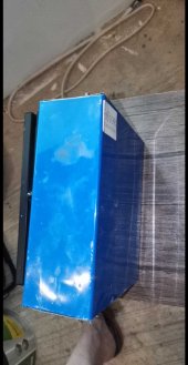
- Cell compression, method? In your case cells compressed with wood plates and rods. All in standing position. Very good.
That's what I thought.
Yet... This probably is the cause of the problem.
As my 152ah cells where slightly bloated, they also received the same compression the 280 did, and probably, 10 cells (4* 280, 6 152) in a row is too much.
My best guess is that the delamination that occurred during several months with charge/ discharge and expansion of the other cells, compression the ones that are slightly bloated...
Made one go self discharge.
- Cells setup? In your case you did a 2p4s.
S16, 5 strings.
And you wrote 48V so you have to make a 4s from that (can not see what connects them in the pics). So it is a 2p4s4s system. Really not ideal but can work. BMS only saw the average V of two cells. (possible cell overcharge and overdischarge without BMS interaction)
2* S16, (one 280, one 152Ah on the bottom layer + "S8" half of S16,spilt over 2 Layers, connect with 35mm2 cable and lugs.
Second layer, Bus-bars yet placed.
S*S15, again one 280Ah, one 152Ah.
All 5 X S16 join the same backbone bus-bar.
Each cell has its own (or was supposed to get its own) cell PCB.
DIYBMS cell unit is "stand alone" for set Balance level, even without the controller unit, they still start to discharge at the set level.
(For me 3.65v)

That's right, 80 modules who are in series, not to measure, each unit does this individual, but to communicate with the controller.
And yes, also 5 controller boards.
- Temperature sensors, BMS placement?
Temperature sensor I placed on the positive terminal.
I could have chosen negatieve, or on the bus-bar.
Last one was more challenging then I expected, so Shrink-wrap around the terminal, with inside shrink wrapped thermal sensor.
It doesn't need to be really accurate.
What it does need to tell per cell (how many BMS have per cell temperature sensors??)
If the bus-bar/terminal contact is warmer then that of the other contacts, possible warning for a failure.
This might be new to some people, but a bad contact, what can happen due numerous reasons even after months, is first shown by increased heat during high charge or discharge.
Soon later by strange voltage readings.
I can not see in pics what goes where. Cable management needed. Where is the 16s BMS? I see something (BMS, balancer?) on top of the cells
.
Lol
Yah, temporary, during installation of all the wires, the active balancer. (with metal casing!!!) Was laying on top of thick plastic, on top of the grubscrews.
Later that day, mounted at the wall, where you can see on other pictures a white square print...
So, not for long
Very bad placement. And it is connected to 4 cells.
It's connected to the lower layer 280Ah cells
Second active balancer was laying in front on the floor, for the 152Ah cells.

You can see on. One the smoke damage.
It cant be right if your setup is a 48V system. You should use a single 16s BMS and/or balancer, and not 4 times 4s.
BMS: not installed yet.
While for some people this is "the worse thing anyone can do", the cells in use where "24/7" monitored.

Now I could have chosen a picture where the cells are nicely sitting at 3.300v with 0.001v difference.
If that makes people happy... I. An share also.
I have about a few hundred of screenshots.
This one is during top balancing.
And for the few who have insight in top balance voltages, will agree, this is a really nicely balanced pack
The Bluetooth active balancer is perfect battery management system.
Only thing it can not to is disconnect.
Lucky that is something a human still can do
Stop charge or discharge
- Next (top) level cells seem to be too close. I would leave at least 15cm (6 inch) air gap (with more even easier the maintenance). Is there a floor bellow the top cells? The cells sometimes release a bit of electrolyte (not really in upstanding position but better safe than sorry).
5 cm more, perhaps. It would not have stopped the fire, but would have extended the BMS wires with 5cm.
30cm space between the layers would have worked, enough room to do maintenance on BMS cell PCB if needed, so no extension.
But... I choose different.
More compact.
For airflow it's enough.
Cells where lifted 1/2 inch of the floor, air circulation for sure efficient.
- Did you do a proper top balance of the cells ? What were your procedures, how did you do it ?
Answer already given, regular basis.
With the BMS.
Before installation?
Absolutely.
Charge each individual cell up to 3.65v.
That was done by placing them in sets of 4, with BMS, using a car battery.
As soon any reached 3.6v, I disconnect the set, and manually charged each up to 3.65v.
As you understand, that took several weeks, and in that period the cells who where automatically reducing the voltage where topped up.
At the end all cells where "one large string" (some zigzag) in parallel, connect with Bus-bars and cables, and charged to 3.65, each cell, and kept like this for a few days.
Each cell during placement was 3.65v.
None of those cells made the fire.
They did not have Bus-bars yet ..
The lower layer was started in the same way.
As the idea was to connect all 5, understandable that I was keeping the cells at top, as much as possible.
Yet... Rain season, no sun.
The inverter is set to stop at 48v.
2.9-3.0 per cell
About an hour before the fire I checked, and that was the voltage.
- Copper busbars on alu terminals. Rusty busbars.
I don't see where you think you see rusty bus-bar.
They are all electroplated thick copper bus-bars.
You can find my thread about it on this forum.
I obtained ox-guard, special order from the states, $45,- and 6 weeks.

Terminal was scrubbed, cleaned with acetone, and ox-guard applied.
Same for the tin plated Bus-bars, Time between cleaning and mounting the bus-bar with 3.5-4Nm torque, less then 2 minutes
- What was charging the battery ?
early morning during rain season, 300-400 watt charging.
43 panels, 27* 325w, 16* 345v
3 X hybrid Revo II inverter
At that time..
About 100 watt charge each.
07.30, clouds, light rain.
- What was discharging the battery ? Inverter (size, type?), direct load ? Max discharging current/watt estimate ?
3 X 3.2kw inverter, each charge 100w
- Cells electric separation? Standing on a non conductive base? Non conductive separator between the cells ?
Pained iron for the 280, who each have plastic sheet on bottom and naturally all cells have their blue wrap.
The 152 are same wide as the 280, more slim, and lower
They where raised with wood.
Besides this, no special separation between the cells.
I have seen that Eve does this, yellow sheets between the cells.
I've never seen Will Prowse or David Potzz do this.
Perhaps it's needed, I don't know.
- Cells placement? Shed, garage, inside/outside? On the ground, on shelves, ... ? How protected from fauna (rodents, bugs) and flora ?
Inside our bedroom!
Or actually, a walk in closet, cooled by the airconditioning from our bedroom.
We have over 40 cats..
(Different story) we still occasional see mouse droppings in out room, bathroom, kitchen etc.
Gecko's, snakes, scorpions, ants, beetels, and many mosquito...
(+ A lot of spiders) not to forget the frogs..

Few days ago.. this one on the bed...
Scary!!
25-28 degrees, Aircon.
35mm2., Breakers.
24/7 off grid setup.
Only stopped at 48v if it's too low.
And 10% is a high safety margin.
- Where the battery floated? So SoC >95% and float V > 3,4-3,45V/cell ?
DIYBMS, not yet installed.
Cell Volts in BMS a multimeter?
Yes, absolutely.
I will try to make tomorrow.