diy solar

diy solar

Shunt snapped and caused a firešŸ”„

48 volt shorts get you plasma.

Arc welding is done at around 18-25 volts.

Spray transfer is like 28 volts and above.

All those smoke detectors will do is allow you to know your house is on fire so you can log into your cameras while you're at Disneyland and watch it burn down.
 
48 volt shorts get you plasma.

Arc welding is done at around 18-25 volts.

Spray transfer is like 28 volts and above.

All those smoke detectors will do is allow you to know your house is on fire so you can log into your cameras while you're at Disneyland and watch it burn down.
:unsure::unsure::unsure: he ain't wrong ya know!
 
48 volt shorts get you plasma.

Arc welding is done at around 18-25 volts.

Spray transfer is like 28 volts and above.

All those smoke detectors will do is allow you to know your house is on fire so you can log into your cameras while you're at Disneyland and watch it burn down.
yeah a fancy smoke detector canā€™t fix negligence
 
Last edited:
If people are brave enough to post details of their accident for others to learn from, I think they deserve that comments are moderate in tone and not disrespectful, otherwise how likely are others in the future to keep their failures off the boards, instead of risking it?

Forum moderators should remove disrespectful comments IMHO, for the benefit of all users.
 
Don't be too hard on him.

Sure, there are lessons learned (expensive lessons, thankfully not worse). But berating him isn't going to help anyone. Everyone starts somewhere, and maybe to his understanding and knowledge he did just fine.

We ALL overlook things sometimes, or do things we think are fine then learn later OOPS guess not. Don't pretend you have everything down perfect every time. Maybe your own DIY ESS was, but I am certain you've had your own share of oops moments in your life. Everyone has.

Being condescending "holier-than-thou" never helps anyone.

We've learned and/or been reminded that:
1) Particle board isn't any good for this sort of thing (some of us may have suspected or known that already, others may not have)
2) Ambient temperature/humidity plays a role and that has to be accounted for in any ESS design
3) Wire length between the battery pack and the first crucial protective device (properly rated fuse and/or breaker) should be kept as short as possible, and protected as possible
- 3a) ideally, the first device should probably be a T-class fuse. A breaker after it at some point as a convenience and second line of defense is never a bad idea. I'd have the fuse rated a bit higher than the breaker so that the breaker has a chance to trip first before the fuse blows. Easier to flip a breaker back on than to have to replace a $40 fuse (or however much they run these days, I have not looked recently).
4) Everything should be mounted on an appropriate, sturdy surface - no hanging connections, no excessive weight on terminals from hanging wires, etc
5) BMS quality is very important - Daly doesn't fit that criteria, really, for larger scale ESS (maybe something small it is ok but I wouldn't do it personally)

There's more but that's just off the top of my head.
 
The Dewalt shelves that Will also has mentioned are super sturdy and I think would even survive a fire. This isn't great pic of showing all the shelves but you can see a shelf consist of wire rack that sits in a groove with hefty yellow metal braces underneath. In my case I added the extra protection some have mentioned of using rock wool on the sides, top of top shelf, and below bottom shelf. Between the middle shelves is cement board so that if something does happen to cells below a shelf carrying cells itself there is chance it won't affect the shelf above. There is a thick sheet of polycarbonate panel on top of the wire racks to physically protect cells from the wire rack. Polycarbonate also has much higher temp rating then acrylic which I've seen some use. Also note the tubing around the threaded rod to protect cells from any potential physical damage. Threaded rod goes through 1.25"x1.25" angled aluminum on the outside of the plywood since the plywood by itself would not be enough.
View attachment 198495

Do you have a thread on your battery build? I'd like to see more pictures of it from more angles and showing the busbar and fusing?
 
If people are brave enough to post details of their accident for others to learn from, I think they deserve that comments are moderate in tone and not disrespectful, otherwise how likely are others in the future to keep their failures off the boards, instead of risking it?

Forum moderators should remove disrespectful comments IMHO, for the benefit of all users.
We usually handle whatever gets reported.
 
the rest of your dissertation was spot on, but I take issue with this, they should be twisted/paired together to avoid the impedance and voltage loss... at least that is what i was taught many years ago. maybe current theory is different. if so please site references .
I think, I'm not on certain ground here, but I think that the purpose of twisting is to equalize the exposure to external fields. Like a twisted pair communications cable is twisted to equalize interference.

And the effects of two wires interacting with each other, ignoring external fields, only requires maintaining their proximity to each other.

So for two DC wires, ignoring all external fields, running together in parallel is just as good as twisted.

But I could see a counterargument that twisting also equalizes their inductance to other metals around them.
 
- 3a) ideally, the first device should probably be a T-class fuse. A breaker after it at some point as a convenience and second line of defense is never a bad idea. I'd have the fuse rated a bit higher than the breaker so that the breaker has a chance to trip first before the fuse blows. Easier to flip a breaker back on than to have to replace a $40 fuse (or however much they run these days, I have not looked recently).

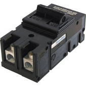
I was going to put class T in series with 200A main breaker for my house. Intention was fuse blows in the event of catastrophic short, breaker handles overloads.

Comparing trip curves, I selected 400A fuse. It looked like at 400A current, breaker would be guaranteed to trip first, while above 2000A fuse would be guaranteed to blow first.

I ended up not installing it for space reasons.
I had been thinking I didn't want to have to deal with PG&E shutting off power to replace breaker, but this model is plug-on bolt down so easily done hot, anyway.

1708961593744.png
 
First off, I'm sorry for your loss; this looks obviously expensive.

A few points:
- A few people brought up the breakers. Although not the root cause here, AC breakers don't work in DC environments. It's not a matter of over-current protection, an AC breaker will trip if overloaded with DC amps, but that's not the problem. It's all about the breaker's ability to extinguish the electrical arc when the contacts are opened under load. DC current can sustain a gap over a magnitude greater distance than AC current can, and DC breakers use permanent magnets to quell the plasma, which is also magnetic. This is also why DC breakers are polarity specific. Someone made a comment they don't "like" using DC breakers... well, this isn't the type of "preference" compatible with popularity metrics.
- What material are the bus bars made from? They look to be aluminum stock from the hardware isle. Were they supported by some means? In the photos they appear to be laying physically on top of cables of opposite polarity. Keep in mind that aluminum under compression, as it would be at the point of a mechanical lug attachment, will compress and over time migrate away from the compression. As the connection loosens the resistance increases, and so these need to have their torque periodically re-checked.
- I have never seen a free-air, base-less, shunt. A shunt like that would have to be designed to bolt into some fixture like one that holds a large fuse, not dangling with the elements under physical tension. Also, all shunts are resistors and by nature will get hot under load. Even under rated load. The photos show them mounted over a combustible surface, no enclosure, no strain relief.

In the next battery array you build I might suggest some considerations:
- Avoid use of permeable materials that are under loading forces. That could be weight load, tension load, compressive load, etc. Wood might make an adequate insulator at 48V DC but that only holds true as long as it remains clean and dry.
- It doesn't always require overcurrent to make hot spots. Think in terms of connections, each current-carrying junction poses the risk of becoming overheated if the tension holding it together diminishes. Aluminum compresses over time, especially with heat cycles, and needs to be retorqued when involved in a junction, so design your system so these junctions are visible and accessible.
- Provide securely fastened routing paths for all current-carrying cabling. Avoid instances where a dangling heavy cable's jacket is exposed to an edge that ends up supporting its weight. The focused pressure on the jacket of a cable passing over and edge will result in compromised cable insulation. Cabling making vertical transitions should be secured to a vertical surface with its weight being carried by multiple clamps/ties as-needed.
- Long runs of DC cabling should have the positive and negative conductors run parallel to each other. This will minimize impedance and voltage loss to inductive currents being created by the current flow in the cable. When parallel, the positive and negative conductors' ability to induce eddy currents in surrounding material is mostly cancelled out.
- Consider putting all-thread into PVC pipe sleaves, or some such material, to that the sharp threads to not pose a chaffing hazard to the cells. Also, use a rigid steal piece of steal, like 12AWG 1.5/8" Unistrut, or similar material, for the endcap span between the two rods. This eliminates the problem of warpage when a permeable material like wood is carrying a mechanical load.
- Enclose all of the DC components and connections to protect them from the environment, and the possibility of any conductive foreign material entering the area.
- Approach design from a "what if..." perspective. "What will this connection affect if gets too hot? What if this wire gets yanked? What if this material is exposed to high humidity or even water? What if something metal nearby topples over near and into this? What if there is a smoke or a fire?" Think in terms of every component having the desire to fail with a radius of destruction around it while doing so.

A regular inspection of all the components under full load is a healthy practice. Keeping everything clean will help here too. I have a FLIR infra-red camera attachment for my phone that works brilliantly for spotting hot spots. Anything getting hot has potential disaster in its future.

I hope it works out recovering from this loss.
This was a great read. Thank you
 
I second not using Daly. Mine personally sucked.
what did you go with? I am currently using DALY's and other than some strange quirks with how they report SOC and whatnot have not had any major issues with them, though I do not think they are even remotely the best out there.

I bought a "Chargery" system a while back as i wanted to experiment with it, but never installed it. its still new in the box. i just saw too many questions popping up about its solid state contactors and wimped out.
 
I started with Daly - I had experience with them on E-bike battery packs, but on the 48v big packs, they were not working well to keep cells balanced. Sometimes the Daly BMS would not trigger balancing even if it should have (ie cells above the min to start balancing but BMS not balancing) and if the charge current dropped off during balancing the BMS would stop and not restart balancing even when charge current returned. Sometimes the Daly BMS would refuse to connect to BT and pi$$ me off.

Since I was building a pack twice per year, slowly building up the ESS, I switched to JK BMS's early and these just worked. I bought all my JK's long before the recent (last Fall?) thing where some members had them revert to default settings 'out of the blue' without operator input, I read this was a glitch and fixed with software update. Anyway, in my ESS all the BMS's are JK's now, they use 0.6A balancing, set to start above 3.4v per cell, and the JK's keep all the cells in balance very well. If I build one more pack (when I build one more pack) It will get a JK BMS.

A few things to know about the JK BMS set up - in the settings you need to set how many cells and their capacity in Ah, then calibrate the voltage and the current - ie get a reading with a good multimeter and set the voltage in the BMS to match, ditto with current flow, then the BMS will run well.
 
what did you go with? I am currently using DALY's and other than some strange quirks with how they report SOC and whatnot have not had any major issues with them, though I do not think they are even remotely the best out there.

I bought a "Chargery" system a while back as i wanted to experiment with it, but never installed it. its still new in the box. i just saw too many questions popping up about its solid state contactors and wimped out.

Tried for JBD per recommendations on here but none were available for my 24V setup. Went with JK 150 Amp.

You can actually see it balancing the cells. The Daly never seemed to do anything.

The Daly amps reading was always jumpy but would go totally nuts if the charge or discharge mos turned off.

It would read 70 amps flowing in even when no charging current was applied so the state of charge reading would climb up to 100% while cell voltage dropped so then it would not reactivate charging because it would now think soc was at 100%.

It eventually started showing 300 amps flowing in with 1.8 volts per cell...anyways...don't wanna muck up this thread. No idea if the jk will do better once low temps hit until next winter....so far I like that I can see it balance.

Wonder if the OP's dalys failed to cut on overcurrent and that helped moved whatever failed along quicker.
 
I have four of the Overkill branded JBDā€™s and they have been very good. My build which is linked in my signature uses a 300 amp class T fuse very close to the battery and itā€™s there as a last resort ā€œoh $hitā€ safety. Each battery is protected from overload by a 100 amp rack mounted breaker. The cells are on steel shelves originally designed for AGM telecommunications batteries so weight wasnā€™t a concern. I agree with most of the sentiments that the OPā€™s choice of shelving probably was the cause of this failure. Some of his wiring practices were questionable but would likely have worked just fine if the shelf had held. Better wiring etiquette might have prevented the fire when the shelf failed. I applaud the OP for having the balls to show us what happened and providing a valuable teaching moment for anyone thinking of building their own batteries. As I said before, these batteries are capable of massive potential and demand respect.
 
Tried for JBD per recommendations on here but none were available for my 24V setup. Went with JK 150 Amp.

You can actually see it balancing the cells. The Daly never seemed to do anything.

The Daly amps reading was always jumpy but would go totally nuts if the charge or discharge mos turned off.

It would read 70 amps flowing in even when no charging current was applied so the state of charge reading would climb up to 100% while cell voltage dropped so then it would not reactivate charging because it would now think soc was at 100%.

It eventually started showing 300 amps flowing in with 1.8 volts per cell...anyways...don't wanna muck up this thread. No idea if the jk will do better once low temps hit until next winter....so far I like that I can see it balance.

Wonder if the OP's dalys failed to cut on overcurrent and that helped moved whatever failed along quicker.
well some thought that the DALY's might have been a concern. hence my asking. I think you just got a bad one honestly as other than not reading low current draws and low current charging (throws off the SOC) Mine have all worked including low/high temp shutdown. I have my SCC set to never overcharge so the BMS is a backup in that regards same for genset charging that is needed once or twice a winter season, so I cannot vouch for that as the SCC and the charger in the Magnum inverter have covered those issues to date.
 
I have my SCC set to never overcharge so the BMS is a backup in that regards
However this will rely on all the cells being below high voltage cut off. The SCC doesn't know if one cell is at 3.77v if the other cells are low enough to keep the total pack voltage below SCC voltage setting. The SCC relies on the cells being balanced.

Thus was my issue with the Daly BMS's - they were NOT holding the cells in balance. This was quite concerning to me. Several times I was checking the charging and one Daly BMS had switched off charging due to a high voltage cell, made me wonder, what if it Hadn't switched off charging. Changing to JK's was a PITA - having to remove each pack and change BMS, plus the cost of the new equipment. I can say after more than a year of operation, the JK's keep my cells balanced, and I trust them.

I can imagine the OP running his rig, expecting the SCC to control charging, until one day...

If the BMS is the emergency back up to the SCC settings, we need the BMS to reliably work.
i think part of that is how well the cells are matched. i had the same problem and pretty much fixed it when I personally capacity tested all of my cells and also matched the IR as close together as possible. as a result out of 68 cells I removed the lower 20 of them (1 16 pack and the four spares) and rebuilt from four packs to 3 packs and now the DALY's keep the cells in balance.
I think it is just the fact that the DALY units are designed for matched and batched cells only in all reality as the resistor style balancing only works on minor variations.

I have 4 of the NEELY balancers that I bought as i thought that i needed a bigger balancer. i could probably put one of them to work on the "bad cells" and it would keep them balanced, but why? (not to mention i could not get the first one out of the box to work) so there is obviously some more experimenting to be done.
 
I have 4 of the NEELY balancers that I bought as i thought that i needed a bigger balancer. i could probably put one of them to work on the "bad cells" and it would keep them balanced, but why? (not to mention i could not get the first one out of the box to work) so there is obviously some more experimenting to be done.
For fun!
 
Back
Top