diy solar

diy solar

Shunt snapped and caused a fire🔥

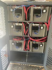
Those cables leading to the pack never went under that shelf bracket and they had enough slack on them that if the shelf/bracket broke and it dropped they still would not have been out of length and pulling on the breaker.

The breakers were for Positive and Negative.

If the weight of the pack were too break the shelf it would have been the other end where the battery weight is all going from middle to back of the shelf, the front end was barely holding anything.

It's really hard to tell what damage was done during the event and what was done from the chemical extinguishers, but if the panels were really struggling with the weight then being soaked and sprayed I would have expected all or at least some of them to have given in and collapsed.

I'm not sure what happend in the end, and I'll have to spend a lot of time cleaning it all up.

It looked to me like the cables went to a battery pack that sat on the shelf that was supported by that bracket.

So I hypothesized that the shelf gave way allowing pack to fall which pulled the wires down onto the bracket cutting into the insulation and allowing the positive/negative to short to each other.

250 amps on the Daly @ 48 VOLTS is like 12,000 watts of heating into those two cables plus whatever backfeed made its way through the 300 amp breaker from the other packs.

You potentially had 300 amps breaker plus 250 amp bms for a grand total of 26000 watts into those cables, right?


But you think the cables were long enough between the breaker and battery pack to prevent them from being strained against the top of the shelf bracket if the shelf let go and allowed the battery to drop?

If so, how did the the burn marks on the top of the bracket happen and why did the cables melt in half?

Edit: Point being, lots of heat can be generated without reaching the limits of the BMS(s).
 
Last edited:
I'm now looking at putting the batteries inside an used gun safe strip out the inside and weld in steel shelves each bank. Put a stove pipe on the top go out though the roof of my shed and a fan at the bottom to feed air in it's way overkill but I can go on a business trip and not worry about it. Lot of these used cheap on FB, or Craigslist.
 
I'm now looking at putting the batteries inside a used gun safe strip out the inside and weld in steel shelves each bank. Weld in a stove pipe on the top and a fan at the bottom to feed air in its way overkill but I can go on a business trip and not worry about it.
Batteries in a cabinet are giant pain in the asses to deal with.

Which is why my boxes are configured to take up as little room as possible…which has its own issues.

I used an 18 inch depth one (not a gun cabinet). I suggest 24 inch ones.

Takes two strong guys to put in or take out the boxes from this one and getting the 4/0 cables in place (all cut to 12 ft) is a giant pain in the ass. 4/0 is overkill here though. Smaller wire would be much easier.

IMG_5830.jpeg
Had to install 3/8 all thread down the center for extra support even though the weight was under the manufacturer’s weight rating.

Another product to consider. Rockwool and others make a very dense mineral wool board product. It’s similar to “comfort board” but denser. It’s used in kilns, rod cabinets, high end sound proofing, etc.
 
Last edited:
Excess current doesn't cause any harm, if the BMS does it's job. If not, the breaker should trip and cut off the current, but only if the breaker is sized correctly. Looking at a trip curve, it could take considerable time for my 125A breakers to trip with 168A current.
I wonder what the OP's breakers were rated for, and if this perhaps lead to the dominos falling - overheated cables short to the edge of the shelf-angle leading to heating up and fire, venting the cells that then also catch fire, collapse the shelf leading to the broken shunt and other damage we see.
Re-stating one failure mode possibility - so we can compare to the new data provided, see if we gain some insight:
I explained just above but the breakers were actually turned off after everything happend, how ever I believe all the BMS had cut off anyway, possibly damaged by the fire fighters, over current spike, heat.
Breakers didn't trip. They were manually turned off after the fire was under control.
All the stats I can see in home assistant show nominal Cell voltages in charge state 3.3V~ 40-70A incoming current to each pack, BMS were 250/125Charge Daly, Shunt 300A rating.
BMS's are Daly - 250A discharge, 125A Charge.
Cells were at the top half of charge cycle 3.3v
I will note, Pack 6 the bottom one had a completly destroyed BMS, I haven't got a really close look at it appears the front 2 cells Vented/Burned.
Pack 6 BMS completely destroyed - we will come back to this statement below.
Pack 6 spiked from 30C - 46C recorded at 12:17:22.
32 seconds later, after spike in temp ...
Pack 6 last communicated with home assistant at 12:17:54 - Charging current reading
What was this last current charted? was there any evidence of rising/falling current?
for 250A you had to size up to 3P.
250A breakers

Pack 6 I got a ding on the breaker that was attached so appears it never closed {My edit: think you mean never opened} how ever that attached BMS must have shut down the pack and it doesn't appear all that damaged.
Earlier statement says BMS 6 was "completely destroyed" - maybe you meant to say pack 10 BMS, where the fire was hottest?

One item that is not clear: which shunt is the melted one? Is this from pack 6 or pack 10? <----OP?
Second item: What cells are these? - Are they all the same?
If not all the same cells, what cells are on pack #6?
What were the Daly program settings for over-voltage, and over-temperature?


Let's see what this new information suggests:
The cells are charging, 40-70A per pack (400-700A total to the ESS)
One BMS on pack 6 records a high temperature spike, and just 32 seconds after this goes "dark" - loss of comms and records a final current reading of _____? OP can you tell us?

None of the 250A breakers trip during the event.
OP expects the BMS's shut down the packs, however what if Pack 6 BMS didn't shut down?, only other BMS's did. This would spike the current to pack 6, and since the BMS-charge current is rated at half the breaker current, it's failure to disconnect could allow very high amperge to flow to pack 6 - upwards of 400 + amps. The trip curve for the 250A breaker will allow over current for a period of time. Did pack 6 have a 'runner' cell that hit over voltage and vent due to BMS-6 failure?
Did the shunt/BMS melt under the high amperage and start the wood on fire, or ignited the cell vent-gas?


Very interesting scenario, I think there is more we can all learn from this with the OP's help.
In my own system I have long wondered: What is the system protection if a BMS fails to shut-down a pack on a cell over-voltage event?
 
Re-stating one failure mode possibility - so we can compare to the new data provided, see if we gain some insight:

Breakers didn't trip. They were manually turned off after the fire was under control.

BMS's are Daly - 250A discharge, 125A Charge.
Cells were at the top half of charge cycle 3.3v

Pack 6 BMS completely destroyed - we will come back to this statement below.

32 seconds later, after spike in temp ...

What was this last current charted? was there any evidence of rising/falling current?

250A breakers


Earlier statement says BMS 6 was "completely destroyed" - maybe you meant to say pack 10 BMS, where the fire was hottest?

One item that is not clear: which shunt is the melted one? Is this from pack 6 or pack 10? <----OP?
Second item: What cells are these? - Are they all the same?
If not all the same cells, what cells are on pack #6?
What were the Daly program settings for over-voltage, and over-temperature?


Let's see what this new information suggests:
The cells are charging, 40-70A per pack (400-700A total to the ESS)
One BMS on pack 6 records a high temperature spike, and just 32 seconds after this goes "dark" - loss of comms and records a final current reading of _____? OP can you tell us?

None of the 250A breakers trip during the event.
OP expects the BMS's shut down the packs, however what if Pack 6 BMS didn't shut down?, only other BMS's did. This would spike the current to pack 6, and since the BMS-charge current is rated at half the breaker current, it's failure to disconnect could allow very high amperge to flow to pack 6 - upwards of 400 + amps. The trip curve for the 250A breaker will allow over current for a period of time. Did pack 6 have a 'runner' cell that hit over voltage and vent due to BMS-6 failure?
Did the shunt/BMS melt under the high amperage and start the wood on fire, or ignited the cell vent-gas?


Very interesting scenario, I think there is more we can all learn from this with the OP's help.
In my own system I have long wondered: What is the system protection if a BMS fails to shut-down a pack on a cell over-voltage event?

I'm going to guess the melted shunt is on the pack that shorted.

It melted from the current flow back-feeding out of the other packs to where the cables shorted out on the shelf bracket.
 
I'm going to guess the melted shunt is on the pack that shorted.

It melted from the current flow back-feeding out of the other packs to where the cables shorted out on the shelf bracket.
I looked at this too, but:
What would have been the cause of the cable shorting to the frame?
Looking for a trigger here, those big cables are unlikely to "just short out" out-of-the-blue.
OP says it can't be due to a shelf failure, because the cables were plenty long, and the shelf is unlikely to "just fail" without something to cause this - something fell on it" okay what?

Suppose the cable short is a result of the fire, not the cause of it, now what do you see starting the string of events?
 
I looked at this too, but:
What would have been the cause of the cable shorting to the frame?

Arresting the falling battery pack. Those shelf brackets are somewhat sharp. Not like a razor but you could rake a piece of wood across them and get a whittling effect.
Looking for a trigger here, those big cables are unlikely to "just short out" out-of-the-blue.

I don't think they did. I think they were asked to arrest a falling battery pack.

OP says it can't be due to a shelf failure, because the cables were plenty long,

I need clarification here. OP thought we said cables were going under the bracket.

We or least me assumes the pack was sitting on the shelf. I don't know which end cables were attached to but it wouldnt really matter.
and the shelf is unlikely to "just fail" without something to cause this - something fell on it" okay what?

The particle board itself failed. The stuff that comes one those shelves isn't 1980's hernia-inducing overlayment. Its 1/2 thick crap that always has sawdust flaking off it. You can see it already distorting in one of the other photos.
Suppose the cable short is a result of the fire, not the cause of it, now what do you see starting the string of events?

No idea other than overcharging albeit my brain doesn't work that way.

It would be something that started a fire first so a short somewhere else or overcharging.

To me the shunt failed due to the short and is definitely NOT the cause.
 
So each cell weighs about 10-11 lbs. With all thread etc, you're looking at at least 180 lbs under dynamic force that had to be arrested by the battery cables.

Welding cable insulation is the softer, more mealy stuff and is more easily damaged than vinyl automotive cable.

For reference that's the Olympic barbell plus 2 45 lb plates plus 2 25 lb plates, approximately.
 
I will note, Pack 6 the bottom one had a completly destroyed BMS, I haven't got a really close look at it appears the front 2 cells Vented/Burned.

Pack 10 Above it, the BMS is still atached and outwardly doesn't look damaged how ever that pack looks to have lost the front 4 Cells at least.

Pack 6 last communicated with home assistant at 12:17:54 - Charging current reading
Pack 10 last communicated with home assistant at 12:12:21 - Charging current reading

Pack 10 didn't have any temperature updates recorded by home assistant for hours and nothing as the event happend.
Pack 6 spiked from 30C - 46C recorded at 12:17:22.

So I guess the event happend right around that time.

I went to work and took my bike out of the garage at around 6:30AM that day and everything was fine.

So pack 10 seems to be the culprit here, first to go nuts and loss of data hours earlier. Pack 10 being on the end upper shelf.

Pack 6 on the lower shelf with the destroyed BMS kept working another 5 minutes. - I would assume the BMS being destroyed was from the vented cells and the vented cells was from the shelf from pack 10 impacting it. I would also assume that only that end of pack 10 fell to start with or you may have had more venting.

Were the breakers being used as overcurrent protection or just as switches to turn off individual packs?

95mm cables is 3/0 to us Yanks, what type insulation and heat rating? I assume they are not involved in the cause, but want to be complete. (My wife is from Adelaide)

What sort of fusing do you have and where?

Can you post a diagram of one pack including shunts, fuses, and breakers?
 
All this is making me rethink how I'm building out my shelves and I may even put doors on it after all (turn it into a cabinet, essentially).
 
All this is making me rethink how I'm building out my shelves and I may even put doors on it after all (turn it into a cabinet, essentially).
I am planning to update my own system in a few years, I would like (ideally) to have just two inverters, 12kW output each = 24kW. The space saved from my existing 3-inverter set up will allow me more room for expanded ESS.
Like you, I am now pondering new approach: 'fireproof' style room and auto-triggered suppressant in the room at the ceiling comes to mind.
Unlike the OP, for me an emergency response team could be 30-90 minutes to arrive, and they will be an all volunteer group with limited equipment and experience.
 
Points:

1) The unfused portion between the battery and breaker matters. Ensure nothing can contact or damage this portion of cable or bus bar.

2) The breakers themselves should be at the bus bar which combines all packs and

3) Breakers should be sized to trip before bms limit.

4) Insure all battery racking is solid and earthquake proof. Wood that can burn and collapse is probably not good.
 
All this is making me rethink how I'm building out my shelves and I may even put doors on it after all (turn it into a cabinet, essentially).
Not sure if it was this thread or another - I read so many - but, whatever I do I am thinking of enclosing the whole thing with rockwool panels and a couple of fans for ventilation/heat disipation (I know LFP batteries don't need ventilation)
 
Points:

1) The unfused portion between the battery and breaker matters. Ensure nothing can contact or damage this portion of cable or bus bar.

2) The breakers themselves should be at the bus bar which combines all packs and

3) Breakers should be sized to trip before bms limit.

4) Insure all battery racking is solid and earthquake proof. Wood that can burn and collapse is probably not good.


So, for the store-bought variety of batteries I have been using MRBF fuses attached right to the bolt on the battery. Would you start with that or do something different? Also, would you cover the battery tops and between busbars in case something got in there?

I am still researching/planning but I had in mind ....

battery -> MRBF fuse -> switch/contactor/breaker to turn on/off the battery -> busbar -> class T fuse -> inverter

Arrange batteries in N+1 configuration so you can just add additional banks as needed. Wire sizes to handle current load at different steps, i.e. smaller wires from each bank to the busbar then larger wires from busbar to class T to inverter.
 
I am planning to update my own system in a few years, I would like (ideally) to have just two inverters, 12kW output each = 24kW. The space saved from my existing 3-inverter set up will allow me more room for expanded ESS.
Like you, I am now pondering new approach: 'fireproof' style room and auto-triggered suppressant in the room at the ceiling comes to mind.
Unlike the OP, for me an emergency response team could be 30-90 minutes to arrive, and they will be an all volunteer group with limited equipment and experience.
The fire station is literally less than a minute down the road from me and there is a hydrant in my front yard, but I would rather not be the reason they're called. I don't need that kind of excitement in my family's life!
 
Failure modes discussed:

1. From the OP, shunt snapped shorted/arced started a fire, all other damage was a result of this failure.
2. Shelf collapse - shorted cable or other item and lead to fire, all other damage was a result of the shelf falling.
3. BMS failure, cells vented, heat generated lead to ignition.

Shunt failure - what would cause this? OP suggested poor QC at factory. Can't be ruled out from the data we see so far. It would be good to know which pack had the broken shunt, and compare the data from Home Assistant to look for evidence of the failure in the data. A short anywhere in the system would attract current from the entire ESS and the high PV charging current = would lead to very rapid failure and fire, which we see.

Shelf collapse - particle board style weak shelving - heavy packs - one day the shelf finally fails and falls onto pack below. OP suggested the shelves were well within load capacity, a 16s pack of 280A (assumed) cells is about 200lbs, and noted the shelf collapse is at the lightest loaded end of the shelf. High humidity may have been a contributing factor. Evidence against this - even after the extreme conditions of fire and all the materials the fire department deployed, the remaining shelves are all still intact. If the shelf did collapse this still does not clearly lead to a trigger for the failure, as OP notes the cables were long enough not to be damaged by a shelf collapse. Perhaps cell bus below was shorted by the collapse. Shelf collapse seems most likely to have been a result of the fire, not the cause.

BMS failure - OP has data showing rapid temperature rise in pack, BMS's shutting down, which would increase current to operational/connected packs. More data required, but a failed BMS would likely take a longer time than the Home Assistant shows, to lead to a venting cell and utimately ignition and a fire.

I checked on my own Victron Shunt today under 200A PV charging - warm but not hot. Securely bolted to cement board surface, if it did ever melt or catch fire, there are no flammable materials near-by or above it. Best to keep an eye on it, I just added 3300W more PV this weekend, shortly after a change in a system is often when we spot a problem that was not evident before the change.
 
Back
Top