diy solar

diy solar

Learner set up

Ok another silly question please
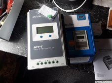
Wire extension for solar arrive so I hook it up and shows working with multimeter but dont work in cheap solar controller
Do I need the mppt better solar charger before this will work,,
Stuck at this point, guess I gota spend 170 to find out ?
Thanks
 
Last edited:
Multimeter says at 2.9.6 that's straight off the wires
...small old panels read 2.2.5
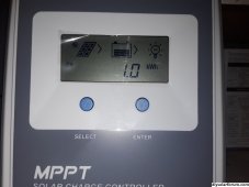
No charging logo flashing on controller, could be underpowered,controller fine when test with small panels
 
Ok FIXED
wire was not hard up in controller,,its now working....your reply made me pull on the wire so big thank you sir.
My test will come tomorrow,,just tryed running TV through inverter and a tablet , it's super cloudy here 5.44pm and inverter holding at 11.5v so definitely have improved it ,Normally would have drained volts and set off inverter alarm so happy it's working,, still goin to upgrade the controller
Oh and system seems ok when both solar systems connected to battery20231127_182932.jpg
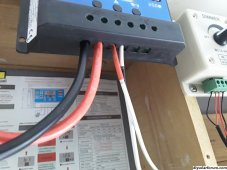
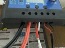
Picture just show wires not made for cheap controller as to why wire not contact terminal,to fat to fit .
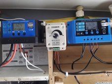
Below both cheapies working and on same settings,,yeh stop laughing at the wiring ,plan to tidy up when other controller arrive.
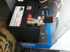
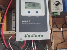
30amp controller straight to batt ,10amp controller for led lights ,inverter direct to batt with fuse between on same +wire for controllers so if some wrong fuse will blow,,well hope so
20231127_194017.jpg

20231127_184110.jpg
 
Last edited:
Update. Rain all morning .only charge to 12.6v
Afternoon sun out TV test 13.6v on controller and inverter read 12.7 holding,,inverter fan louder than normal(600w)
No load the controller did pass 14.4 which it shouldn't have right,hit 14.6,,tryed for photo but never happen again,,I guessing that's the cheap controller, not to keen on that part ,not trust it now since went past preset value and that's just the 30amp controller hooked up.
Seem to have achieved what I was trying to do but new controller cant come soon enough to restore my trust in this set up
 
Last edited:
Hey here's something no one pic up on20231128_182828.jpgScreenshot_20231128-182654_Gallery.jpg
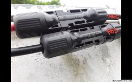
Ok my panel negative and positive on the panel and the solar wire extensions only plugged in reverse (dont know why yet) for the plugs to join.
On my solar controller I had to remember to put negative into positive and positive to negative.
It's not right (red in black) but works as it should but did I buy wrong sort or something---didnt even think to check when I brought
Is that my mistake or the seller put plugs on wrong cable? I write on picture to show neg and pos cable and yes panel cables have - & + on so cant get wrong but extensions are backwards and not cheap
What did I do no bigger but confused on that
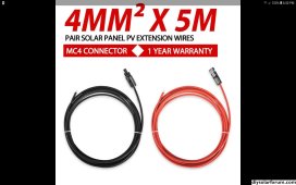
This was wire I got
Screenshot_20231128-185058_Trade Me.jpg
 
Last edited:
Thanks that was one of those not sure if I should say something moments ha
I'll contact the seller so no one else thinks they gone bit crazy,I just used heatshrink so the ends are right colour on the wrong cable now so it looks correct, Thanks for clarifying that
 
panel cables have - & + on so cant get wrong but extensions are backwards and not cheap
What did I do no bigger but confused on that
This was wire I got
It’s because they have to mate; male on one side doesn’t work with a male on the other. It’s supposed to mate male to female.
 
No load the controller did pass 14.4 which it shouldn't have right,hit 14.6,,tryed for photo but never happen again

14.5v~ is good , flooded lead acid batteries can be charged at up to 15.5v

In good sun , the SCC should hold the battery at 14.5v (bulk charge) then when the battery is almost full it should drop to and maintain 13.5v~ (float mode)
 
It’s because they have to mate; male on one side doesn’t work with a male on the other. It’s supposed to mate male to female.
Yip understand that but the colour red is negative and black is positive.Its backwards,anyone else set like that.
 
Last edited:
Yeah, it was either first thing monday morning or end of the day friday, either not enough coffee to get the heads on the right cables or no fu#@s left to give.
 
Emailed seller , no reply yet,I'll keep for spares as I brought another set ,hopefully these right way around lol,different seller
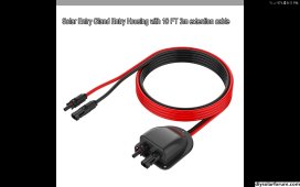
Was just goin to get plain box but this had wires fitted
Screenshot_20231129-201142_Trade Me.jpg
That way can run through the wall properly, new controller should arrive in the morning
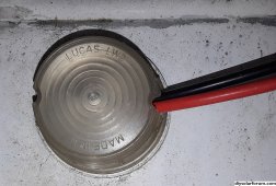
Here's what I did to run old cable into old outside light fitting,hey it works lol,small hole at bottom of cover to let any water out
 

Attachments

  • 20231129_203327.jpg
    20231129_203327.jpg
    1.6 MB · Views: 4
Last edited:
Was just goin to get plain box but this had wires fitted
I haven’t bought a prewired “gland” BUT if you think about this:
The positive(+) out of the panels is black wires typically (because carbon black thwarts UV best) as is the negative(-). So in any case a “standard” extension cable that is MC4 on both ends between the panel(s) and the SCC will “by nature” be opposite color than the pos(+) MC4 and neg(-) MC4 fittings if you are depending on color to plug stuff in: eventually somethings going to be visually reversed.

Polarity is determined by the connector/fitting- they won’t/can’t be plugged in reversed or aka installed backwards by function- the colors are a convenience or ‘safety’ convention but the conductivity will function fine. You can take black and red electrical tape and ‘mark’ the ends like one might do with a 120VAC “traveller” for a three-way/two-way switch, or “round trip” for a wall switch to ceiling fixtures. You simply tape the wire with the right color tape. (I typically use a colored permanent marker on the white AND put tape over that though it’s not required).

I said all the prior to give explanatory context to this:
Alternatively, I have to ask - in your situation with the gland having MC4’s on both ends- does your SCC take MC4 or wire inputs? Because if you have to cut an end for inserting into the SCC, then just reverse the cables in the gland at that time.

One of things that confuses people is that the ‘apparent’ male-female polarity convention expectations are wonky. The male-looking MC4 is mechanically male but electrically female. The reason is that the female-looking plastic connector has an ‘exposed’ (though internal) male conductor, and the male-looking plastic connector has the shrouded/protected female conductor. This isn’t a problem because A) one should never disconnect any MC4 while a circuit can provide current due to arcing damage, and B) a switched two-wire disconnect (a DC Breaker is commonly used) should always be present for the disconnect. So the circuit can be open before unplugging them.

I hope this was helpful.
 
To flash20231130_092251.jpg
It has grounding screw on controller that says must be grounded,,is that just screwed to body of caravan? Manual not say so checking
Or bang a rod in the dirt,,
Thanks
 
Last edited:
Body of the caravan will be fine.
Ah thanks,I should have checked back here sooner,I had nice 10mm Rod with hole in it to bolt earth wire .Well hooked up and running and lots of sun,TV and tablet on and still good voltage holding on the inverter, the inverter fan sure working but no heat anywhere.
Everything will be tidy when new wire arrives , now to read the manual 10 times so I know what it all means
Anyway happy with me minor project and thanks for the info
20231130_124332.jpg20231130_124347.jpg
 
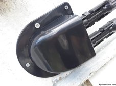
New solar gland and cable arrive ,much better ,this time the positive cable is red lol

20231201_173330.jpg
20231201_201605.jpg
Inside, my home made solar wire holders
 
Last edited:
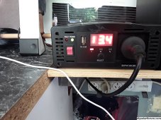
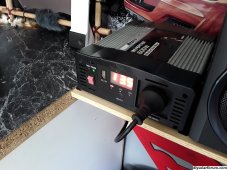
Ok I am curious on my inverter fan,is it normal for fan to pulse,only seems to happen over 12.9v on the inverter
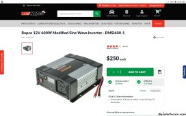
Had this in the car past 5 years but hardly used it,
It was cheap when I buy but now $250 Screenshot_20231205-105057_Chrome.jpg
No idea why,its only 600w and better ones for less money
Cloudy day mppt 14.4v on battery, PV at 28v,inverter on 13.5v with TV on20231205_113339.jpg
Is that fan pulsing a sign of over working or keeping cool not that anything gets the slightest bit warm
Thanks
 
Sounds like the internal thermostat is right at the cut off point so it's just warm enough to kick on and when it does it cools it just enough to kick off. I wouldn't worry about it and I suspect if you put a little more load on there it would just run constantly.
 
that's good I thought it's to old for the new stuff, yeh the inverter fan never starts till 12.9 ,,,12.8 or 12.7v its silent , 13+ and fan is going constant with rpms increasing then back to constant rpm which keeps repeating, full sun it's gota turbo ,I should record it,,its just annoyingly loud .I only have extra load of USB for tablet which barely changes the fan but noticable. Only way I can reduce is turning led lights on . Would be nice to have a new one for good piece if mind and maybe a twin power plug
 
Not letting me add clip
Not liking this fan especially when suns out ,sure is annoying
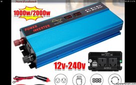
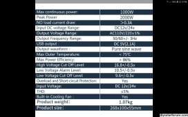
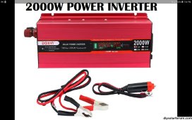
Got my eye on thisScreenshot_20231206-121407_Trade Me.jpgScreenshot_20231206-121249_Trade Me.jpg
Twin plug ,,one I have now I cant use enough power to stop the fan pulsing. Me think this solve that
Also can you use this solar wire for batt cables ? Its gota be better than thick speaker wire that's there now ,omg,,yip works good
Just add doin that seems to be more current,inverter 13.9 & 14.5 on controller in cloudy conditions, fan still doin same thing so I gona get this inverter in picture so it's not hyperventilating lol

Edit,,Screenshot_20231206-195420_Trade Me.jpg,I just brought this, twin a bit out of budget,should be here 2 days so I'll update result
 
Last edited:

diy solar

diy solar
Back
Top