


You are using an out of date browser. It may not display this or other websites correctly.
You should upgrade or use an alternative browser.
You should upgrade or use an alternative browser.
Lifepo4 battery box identification
- Thread starter aklb43
- Start date


aklb43
New Member
- Joined
- Mar 10, 2020
- Messages
- 47
The first post is of someone's build of a 24v lifepo4 battery. I am doing the same thing, and was wondering what the case/box/tool chest was used, so that I may use one as well. I managed to find the exact same tool box at lowe's and will be using it for my build.I’m confused as to what you are looking for. Converting any tool box to an electrical box is a good strategy.
I’m curious as to all the connectors used in your first two photos.
MadMax03
New Member
- Joined
- Sep 21, 2019
- Messages
- 249
I forgot I have google-fu
MadMax03
New Member
- Joined
- Sep 21, 2019
- Messages
- 249
aklb43
New Member
- Joined
- Mar 10, 2020
- Messages
- 47
Yes, this is the correct one. Although, it appears that either would work. I would double check the dimensions in person though. Sometimes ribs and bosses on the internal plastic structure can inhibit room and may need trimming to make work.
Last edited:
learning all the time
New Member
- Joined
- Nov 8, 2019
- Messages
- 145
Yeah man, that is a cool box. This may work for me. I am currently making my own. The only missing piece is the box at this point. I was going to go with 280AH but my shipping got jacked up so I am just going to use two Zooms. Quick and easy but the goal is to be able to remove one battery if needed. I am also looking at the DeWalt DWST17820. Anything that will fit and is stackable. The DeWalt may be too big though

Steve_S
Offgrid Cabineer, N.E. Ontario, Canada
I believe DeWalt and possibly another brand have the same as shown but which can be stacked up to 3 High. It acts like a Handtruck when locked together. but 3x (8 280AH) cells @ 5kg ea = 120kg / 264lbs, I dunno how good that could be. Then add the other stuff too.
A while ago, someone posted a similar setup using the Husky Version with the battery pack in the bottom and the inverter & SCC in a smaller box stacked on it. I can't find it, sorry.
A while ago, someone posted a similar setup using the Husky Version with the battery pack in the bottom and the inverter & SCC in a smaller box stacked on it. I can't find it, sorry.
Diesel Pro
New Member
- Joined
- Jul 21, 2021
- Messages
- 112
I'll be interested in seeing how this works out. I'm looking to do this myself for a 8S 280K setup. Searching for inside dimensions for the box. I found outside dimensions but they are obviously incorrect at 39" tall. They show dolly handle height for some reason and not the box itself.
Last edited:
Diesel Pro
New Member
- Joined
- Jul 21, 2021
- Messages
- 112


Steve_S
Offgrid Cabineer, N.E. Ontario, Canada
Looking good so far, a couple of thoughts though.
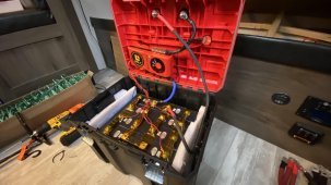
The Buck converter be cautious, IF you are building 24V then get a 30V->12V "NOT" a 24V->12V because when you are charging over 25V that will fry the Buck, I have a 2 junked to learn that lesson. When they fail, they pass full voltage too, THAT is really bad. The only other point is to cover / protect the exposed terminals/lugs from making contact with anything but you'll likely be doing that after the build anyway.
The Buck converter be cautious, IF you are building 24V then get a 30V->12V "NOT" a 24V->12V because when you are charging over 25V that will fry the Buck, I have a 2 junked to learn that lesson. When they fail, they pass full voltage too, THAT is really bad. The only other point is to cover / protect the exposed terminals/lugs from making contact with anything but you'll likely be doing that after the build anyway.
aklb43
New Member
- Joined
- Mar 10, 2020
- Messages
- 47
It looks like the input voltage range of the buck converter is acceptable:Looking good so far, a couple of thoughts though.
The Buck converter be cautious, IF you are building 24V then get a 30V->12V "NOT" a 24V->12V because when you are charging over 25V that will fry the Buck, I have a 2 junked to learn that lesson. When they fail, they pass full voltage too, THAT is really bad. The only other point is to cover / protect the exposed terminals/lugs from making contact with anything but you'll likely be doing that after the build anyway.
- Input voltage range: DC 18-35V; Output voltage: DC 12V(non-adjustable); Output current: 40A; Output power 480W.
I will also have an inline 50amp fuse on the buck converter. The fuse block that will be powered by the buck converter has fuses for each individual terminal.
Here is a picture of the terminal covers I am using.
I will probably surface mount the battery disconnect switch in the back ground. I was having trouble with some of the boxes surface details in order to mount flush, but I think i can figure it out.

F.Y.I. there is an insulated version that is water tight as well…
aklb43
New Member
- Joined
- Mar 10, 2020
- Messages
- 47
I won’t be using compression, as I have flexible buss bars. Compression is only used to prevent the solid bus bars from ruining the terminals. As the cells swell they increase in width, but the solid bus bars attached to each terminal remains the same. This causes torsion on the terminals and damages the cells internally. I won’t have that problem.Is there room for a compression contraption in there?
aklb43
New Member
- Joined
- Mar 10, 2020
- Messages
- 47
Nice, good find. The price is about twice as much as the one I bought though. Also, you'd need to find an alternative way of mounting components, as it has not surfaces to attach zip ties to.F.Y.I. there is an insulated version that is water tight as well…
Similar threads
- Replies
- 20
- Views
- 2K
- Replies
- 69
- Views
- 2K
- Replies
- 16
- Views
- 869
- Replies
- 11
- Views
- 509
- Replies
- 1
- Views
- 97