diy solar

diy solar

LiFePo4 charge problem after reassemble. Any help?

I think you quite possibly have more than 1 issue;

Diagnostics with electrical systems with multiple issues can be challenging.

The other thing with electrical systems is it all seemingly is good until it isn’t; this is important to keep in mind when you finally discover “hey my kettle isn’t working the way it use to”.

I am a novice, but I try to understand “standards”, why, and for the most part follow them.

In Aviation things generally happen where “multiple issues” are the root factors. Your kettle issue could be similar;

Disassembled system for shipping
Reassembled
Energy drained from batteries
Energy put back into batteries
Existing system might have had issues undetected prior to disassembling ( 5 lugs on the battery positive terminal is an indication of this & so is the Waeco & possible the non-communication Epever as I am not familiar with your equipment ).


No history & if you lack details of data from how it use to operate when “all was seemingly good”, it will just make it a little harder to diagnose.

Still, from help from the forum, I’m sure you will get it sorted.

My 2 cents here is I would look a your system under 3 categories;

Charging
Batteries
Loads


I would diagnose the issues under these 3 categories.


The 1st category I would focus on is the battery; BMS, SOC, Connections, Manufacturer’s performance specifications ( charge / discharge ).

2nd I would look at the chargers

3rd I would look at the loads
 
Thanks I went through that already...
When you say this what do you mean, were the connections taken apart and cleaned and reassembled, or just checked for tightness. If those are aluminum buss bars my guess is aluminum oxide and poor connections.
 
When you say this what do you mean, were the connections taken apart and cleaned and reassembled, or just checked for tightness. If those are aluminum buss bars my guess is aluminum oxide and poor connections.
I checked if anything is not tight or feels warm.
Just got of the phone with the person who assembled the battery initially and did also the disassembley and reassembley.

He said on the very first assembly he sanded all bus bars shortly before connecting them. On the recent reassembley he only checked for visible corrosion, and as there was none, he just put it back together.

So, I'm wondering now if the light surface oxidation on untreated aluminium can pose a problem.
 
Just throwing out a few more ideas to consider:
- The bus bars look like they might be aluminum but I am not sure. If they are, then it might not have very good connections.

- Diagnosing this is going to need the ability to measure voltage and current flow in various locations of the pack. At least a volt meter to probe around, and ideally a clamp meter that can fit around the connections.

- What will help a lot is if you can measure the individual voltage of each of those cells and make sure that they are all more or less identical.
Thanks.

Bus bars are aluminium. Bars showed no visibile corrosion on assembly.
The bars worked fine over the last 2.5years.

Clamp meter and Voltage /Amp meter are available.
Measured cells in connected state, as requested earlier. Values are posted. Still waiting for conclusions from the guy requesting that...
 
Last edited:
Get a piece of paper a pen and a volt meter.
Measure the precise voltage of each cell to 3 decimal places and write it down start at main negative, and go to main positive.
Report back here your results.
Did you see my reply message 11 it has the requested measurements you asked for. What do they tell you?
 
Here is a recent thread you might find of interest @LadyRover ;


IMG_1283.jpeg

BMS, want what they want.

Here is why I stated I was confused ( I am not familiar with your equipment, but some thresholds seem to be too high for LFP BMS );

IMG_1276.jpeg


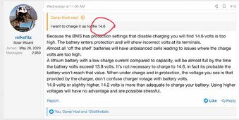
So like I wrote before, I have no LFP experience, but I understand 14.7 & 14.6 is way too high for LFP. In analyzing these issues I always want “Manufacturers’ Manuals & Performance Specifications. Seemingly your system is custom built & you have not posted manuals or specifications. If you can post all the information you posses it can be greatly helpful to “experienced members” here to “see” the issue or a issue;

IMG_1284.jpeg


So, I am STILL confused 🤷‍♂️. But I will be more specific ,,, Why are yor Solar Charges set to these setting. Who set it up this way & why ? When I do not understand something, I ask. So specifically are these solar charger setting too high for your LFP battery & its BMS ?


You are in a “Marine” environment from what I understand.

Your setup in some areas is not “ABYC” compliant & maybe some items are not “best practices” for a marine environment.

Seemingly, someone has built your system & disassembled & reassembled & you then had issues.


When coming across these issues, I find it best to analyze “the facts” & logically with all that you have detailed it really sounds like;

a “connection” ( bad or incorrect with reassembly )
the BMS triggered or partially like @HarryN wrote
user error ( charging equipment not matching LFP parameters )


For me, the best way to sort out where the issue is located is to use a multimeter at different points of the system while charging with various equipment & while discharging & a rest.

Like I wrote before, it seems like there might be more than 1 issue.
 
Last edited:
@LadyRover

You got a manual for your BMS ? ( confused by non-smart );


Also; You have a “Battery Monitor” of some sort ? I did not see what make / model;

IMG_1285.jpeg

IMG_1286.jpeg

If so, can you post the info / manual ?

One Common Connection for shunt based BM is the battery side of the shunt & then possibly the load side to “all chargers”. I mention this as a common bad connection could give you difficulties in charge / higher discharge “inverter / kettle”.

If you have a schematic wiring diagram of your system this can also help if you post it.
 
Last edited:
Here is a recent thread you might find of interest @LadyRover ;


View attachment 205557

BMS, want what they want.

Here is why I stated I was confused ( I am not familiar with your equipment, but some thresholds seem to be too high for LFP BMS );

View attachment 205560


So like I wrote before, I have no LFP experience, but I understand 14.7 & 14.6 is way too high for LFP. In analyzing these issues I always want “Manufacturers’ Manuals & Performance Specifications. Seemingly your system is custom built & you have not posted manuals or specifications. If you can post all the information you posses it can be greatly helpful to “experienced members” here to “see” the issue or a issue;

View attachment 205563


So, I am STILL confused 🤷‍♂️. But I will be more specific ,,, Why are yor Solar Charges set to these setting. Who set it up this way & why ? When I do not understand something, I ask. So specifically are these solar charger setting too high for your LFP battery & its BMS ?


You are in a “Marine” environment from what I understand.

Your setup in some areas is not “ABYC” compliant & maybe some items are not “best practices” for a marine environment.

Seemingly, someone has built your system & disassembled & reassembled & you then had issues.


When coming across these issues, I find it best to analyze “the facts” & logically with all that you have detailed it really sounds like;

a “connection” ( bad or incorrect with reassembly )
the BMS triggered or partially like @HarryN wrote
user error ( charging equipment not matching LFP parameters )


For me, the best way to sort out where the issue is located is to use a multimeter at different points of the system while charging with various equipment & while discharging & a rest.

Like I wrote before, it seems like there might be more than 1 issue.
Just a quick sidenote, I reply more later.

ABYC has zero relevance to me. This is not in US waters, neither is ship or crew from or in the US.

The whole system is built with a minimum budget.
There is no fancy Victron or similar stuff in there. Allmost all parts are from Alibaba.

The system has served us very well over the last 2.5years of full-time cruising. We spent only very very few days in port and are almost always at anchor.

Therefore only a standart LiFePo4 BMS from Daly. You can not set any parameters in there. No data connection whatsoever.

Epever are the MPPT charge controllers you can set their parameters.

We are always switching charging sources of when the battery gets to about 80%.No automatics and no float either.
 
Last edited:
Just a quick sidenote, I reply more later.

ABYC has zero relevance to me. This is not in US waters, neither is ship or crew from or in the US.

The whole system is built with a minimum budget.

Therefore only a standart LiFePo4 BMS from Daly. You can not set any parameters in there. No data connection whatsoever.

Epever are the MPPT charge controllers you can set their parameters.

We are always switching charging sources of when the battery gets to about 80%.No automatics and no float either.

ABYC ,,, I understand & was not referencing for compliance ,,, only for quality control or some reference to what might be considered “Best Practices”. From my end I am just trying to quickly obtain awareness of & as much info on your system here to attempt to locate your issue(s). I’m Canadian & don’t own a boat ,,, but I look at ABYC to learn & design systems that are better than typical RV world specifications for camper vans.

Standard BMS = ( still smart but no Bluetooth & no data ) / got it. How do you “reset it” ?

Epever MPPT ( IN My Inexperienced Opinion ) the charge voltages seem to be set too high for your BMS 🤷‍♂️. What is your opinion of this ?
 
Thanks.

Bus bars are aluminium. Bars showed no visibile corrosion on assembly.
The bars worked fine over the last 2.5years.

Clamp meter and Voltage /Amp meter are available.
Measured cells in connected state, as requested earlier. Values are posted. Still waiting for conclusions from the guy requesting that...

Hey @Supervstech 😁

“Your Up” !!
 
Here the cell measures and more.

Cells were measured with all charge and discharge sources off. Main busbar were connected. Cell closest to negative measured first.

One 3.315V Two 3.315V Three 3.315V Four 3.313V Five 3.313V Six 3.312V Seven 3.313V Eight 3.314V Nine 3.315V Ten 3.313V Eleven 3.313V Twelve 3.313V

Following this I measured with all charge and discharge sources off as follows:

Multimeter across main battery poles: 13.232V
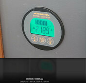
Battery indicator:
13.23V 58.6% charge
Epever 12V Outlet at unit:
13.23V Charge symbol 70% full

Then I measured again with Solar and Wind on. Discharge is off. It's a sunny day, but due to the desert dust in the region around Malta the panels are not 100% clean.

Measures:
Multimeter across main battery poles: 13.6V

Battery indicator:
13.83V 58.7% charge

Epever 12V Outlet at unit:
14.10V Charge symbol almost full
Delivering 7.5A per panel

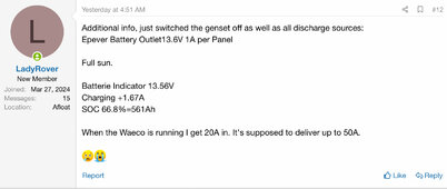
Next I measured with still all discharge sources off but all charge sources on, including the Waeco via Genset. Full sun, panels semi clean, no wind.

Multimeter across main battery poles: 13.9V

Battery indicator:
14.40V 60.1% charge +22A

Epever 12V Outlet at unit:
14.4V Charge symbol almost full
+0A

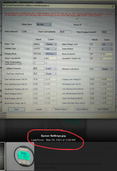
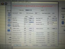
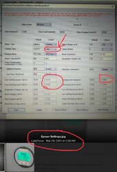
Attached our Epever settings. We used them before successfully they did not change.

THEORY
The Epever "thinks" that the battery is fully loaded when solar is switched on, but battery is actually not full. This because it reads 14.1V at its 12V Outlet when the Multimeter across the main poles reads 13.6V.
Should we change the Epever settings to accommodate that?
If yes, which setting.
Attached a screenshot of the Epever settings (click on the image to see it better) we use and have used successfully in the past.

I did touch all connections, nothing warm, nothing loose, wiring looks good, no corrosion visible.

I'm currently charging with the Waeco/Genset. The Waeco is not a LiFePo4 charger but we use it to "manually" top up when the battery is low. We never leave it on.
Plan to let the Waeco run until the Battery indicator says 95-100%. Even if it's annoying to have to do it. Good plan?
Question remains if it really full then. How can I judge/measure this?

Hope this helps.
I do wonder if something might have been connected wrongly when reassembling.
Thanks for your help!
Cells indicate about 50% charge, so if you are reading 14.anything and not getting any draw, you have a connection issue.

SOMETHING has changed.
Most likely is corrosion.
 
I recommend taking closeup pics of all your wiring and battery connections so we may find an issue.

If you have an infrared camera, you can scan for heat...
 
Back
Top