diy solar

diy solar

LiFepo4 top balancing equipment recommendations

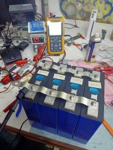
Any chance you could share with me what you did differently to get your power supply to charge at the full 10a? I’m trying to top balance my 8 280ah cells and it is taking forever!

I’ve got it set for constant voltage at 3.6v currently...
My Regulated Bench Power Supply has 3 channels. Two are adjustable 0-30V 5A and the third is 5V only. You can run the two normal channels in series to make 60V 5A, or in parallel for 30V 10A. Your PS has one set of output banana jacks, mine has three sets of output jacks.

Unless you hook a accurate Ammeter inline, you don't know how accurate your PS meters are. The Voltmeters on my PS are off a little bit, so I use a DMM to set the output. On the Amp side I just turn it all the way up. Mine seems to want to top out around 4.95A or so and one channel reads a little higher than the other. Some day I should open the case up and adjust the trim pots for the meters and see if I can get them closer to the actual output.

HY3005D-3.jpg
 
Last edited:
Any chance you could share with me what you did differently to get your power supply to charge at the full 10a? I’m trying to top balance my 8 280ah cells and it is taking forever!

I’ve got it set for constant voltage at 3.6v currently...
Dear all I am currently Top Balancing my new Lifepo4 200Ah cells as well for the first time. The voltage Level were for all cells 3.27V out of the box.

So I have connected them all in series and connected them to a lab power supply as shown in Will s
video.

I was expecting to see a higher charge current @3.65V than 5A.

Can someone explain to me why my cells are not accepting higher charge loads.
I though that they can take much higher charge current with their low internal resistance.

Where do I have the disconnect ?
Are the Lifepo4 high current charger applying a much higher Voltage than the cell voltage to push the current in the Lifepo4 cell?

Found this on the web.

1. Fast "forced" charging: Because an overvoltage can be applied to the LiFePO4 battery without decomposing the electrolyte, it can be charged by only one step of CC to reach 95% SOC or be charged by CC+CV to get 100% SOC. This is similar to the way lead acid batteries are safely force charged.

Thanks for the advice.
Bob
 

Attachments

  • IMG20201114133933.jpg
    IMG20201114133933.jpg
    133.9 KB · Views: 42
Last edited:
I am a newbie on this, who has used a similar power supply on 24V 8 x 280Ah LiFePO4 cell set to a top balance (only) twice now. I wonder what your parallel battery voltage is now, when the Bench supply is OFF ? For me, it took personal hands on lessons to better understand my power supply. I am still a newbie, plus have never seen to total good read on using the bench power supply. What I think I learned after 1st watching Will P's video lesson on this, and from comparing notes in other threads, with my hands on: I could get to the 10 Amps (max of my particular Bench Power Supply) by dialing the voltage adjustment upwards a little bit (like to 3.8V) / and messing with the Current adjustment knob too, to get the red CC light next to current reading light up indicating Constant Current. Seem like I went for AND turning the voltage back down to 3.65V or 3.6V top / to get the green lite next to the voltage numbers would lite up indicating CV Constant Voltage, or I might have had to turn the current knob downward to get the green CV lite ON. ... The Lesson I took in from Will was I could dial up the voltage a bit at the beginning of a Top Balance to get the 10 amp max, BUT ... (I registered this later from forum study and my hands on lessons): I Learned/ & now Believe: Pay attention when voltage of battery set gets near to 3.6V ... Because once it gets to 3.4V, 3.5 V happens much more quickly, and 3.6 can be reached very quickly. So My Take is ... if you are on 3.4V (I would test w Bench Power OFF) ... adjust the voltage knob to get a green CV light next to the top up voltage you are aiming at ... 3.6V Seems like the current knob can be a factor too... When Battery Voltage is BELOW 3.4 V / maybe up voltage adjustment on Bench Power Supply in small as possible increment to get the CC Current up to 10Amps (with CC red light ON next to current reading) , and come back and see what going on hourly or maybe more. If it were my battery set, I would make sure my CV was set at 3.65V with that green lite on next to the Voltage setting on any battery set that was at 3.4V or above; and expect current to reduce way low as battery top balance reaches 3.6V or 3.65V. I am rambling as a newbie, and just giving my opinion here.

... My one other related learning curve lesson I could mention on one very long slow charge cycle on just ONE 3.2V 280Ah LiFePO4 cell: I could never get that one cell above 3.36V ...And that was because that particular one cell was one that proved to be faulty ... (it had less Ahs than it rating, and more internal resistance than my other good cells, depending on much current was flowing in or out). I was trying to getting it fully charged for a follow up Ah test. ... That is another story which I documented elsewhere in this forum / and got that one cell replaced by Xuba for being a below par cell/ for I believe was an unusual problem. Hope to hear you got up to 3.6 V on your Top Balancing session soon.
 
Dear all I am currently Top Balancing my new Lifepo4 200Ah cells as well for the first time. The voltage Level were for all cells 3.27V out of the box.

So I have connected them all in series and connected them to a lab power supply as shown in Will s
video.

I was expecting to see a higher charge current @3.65V than 5A.

Can someone explain to me why my cells are not accepting higher charge loads.
I though that they can take much higher charge current with their low internal resistance.

Where do I have the disconnect ?
Are the Lifepo4 high current charger applying a much higher Voltage than the cell voltage to push the current in the Lifepo4 cell?

Found this on the web.

1. Fast "forced" charging: Because an overvoltage can be applied to the LiFePO4 battery without decomposing the electrolyte, it can be charged by only one step of CC to reach 95% SOC or be charged by CC+CV to get 100% SOC. This is similar to the way lead acid batteries are safely force charged.

Thanks for the advice.
Bob
A lot of bench regulated power supplies only put out 5A to 10A. Other top line ones put out even less. Their main use is a solid accurate low amp power source in electronic design and testing, is the thing that comes to mind. Looking at your pic, my SWAG is your RPS is a 5A model. Just let it do it's thing and it's gonna take 2 +/- days for the cycle to complete. Once the cells get past 3.5V they should start filling up a lot faster. The charge/discharge curve for LFP 12V batteries has it sitting at 13.4V for most the cycle. When they get above/below that changes happen faster. On the discharge side, my 12V battery hangs at 13.4V then start dropping to 13.1V. Below that most of the capacity of the battery has been used. Also above 13.4V is very little capacity. Once you have parallel top balanced them to 3,65V once. Then charging your 12V battery to 13.8-13.9V is GTG.
 
Dear all I am currently Top Balancing my new Lifepo4 200Ah cells as well for the first time. The voltage Level were for all cells 3.27V out of the box.

So I have connected them all in series and connected them to a lab power supply as shown in Will s
video.

I was expecting to see a higher charge current @3.65V than 5A.

Can someone explain to me why my cells are not accepting higher charge loads.
I though that they can take much higher charge current with their low internal resistance.

Where do I have the disconnect ?
Are the Lifepo4 high current charger applying a much higher Voltage than the cell voltage to push the current in the Lifepo4 cell?

Found this on the web.

1. Fast "forced" charging: Because an overvoltage can be applied to the LiFePO4 battery without decomposing the electrolyte, it can be charged by only one step of CC to reach 95% SOC or be charged by CC+CV to get 100% SOC. This is similar to the way lead acid batteries are safely force charged.

Thanks for the advice.
Bob

When charging cells in parallel, 0.1V makes a lot of difference. Looking at the leads your are using - they look quite thin.

As has been said, what is the current max output of your PS, and what have you set it to be (ie in CC mode).

I built my 4s pack, charged them in series to 14V (at 0.3C), then put them in parallel and finished them off at 3.65V for 24 hrs.
That works, too. Just should use a BMS while charging as a series pack, in case one of the cells gets to far out of spec from the rest. But it shouldn't take 24 hours to finish them off in Parallel to 3.65V. From 3.5V to 3.65V should only take a few hours. Maybe take them to 3.65V, let them rest a bit and see where they settle down to and top them off again. I just went ahead and built my battery after they hit 3.65V once. But I was impatient by then.
 
Dear Forum for sure I am using a 10A Lab Power Supply.

And with that low power, max 36W my cables are okay.

Meanwhile it took so long that I connected them to series and charged them up to 80%, paraelled them again to top balanced them.

The classic way in to slow.

Bob
 
Dear Forum for sure I am using a 10A Lab Power Supply.

And with that low power, max 36W my cables are okay.

Meanwhile it took so long that I connected them to series and charged them up to 80%, paraelled them again to top balanced them.

The classic way in to slow.

Bob
Then I am not sure why you weren't getting 10A out of your RPS. You cross the leads to set the voltage and then turn the current control all the way up. My RPS is a 3 channel one, so I have to set the two adjustable channels to 3.65V and max amps each. Each channel on mine will show 5A max, but the cells see it as 10A combined. When it gets close to finished, one channel will drop to zero, before the other one. It's just a slight difference in the way each one reads the cells. If you had two separate 10A power supplies, you could hook both of them up in parallel and the cells would see 20A.
 
Thank you for everyone’s recommendations in the end I went with a Tekpower 40 amp dc power supply. I’m inpatient and it seems like a nice unit. I’ll probablly charge at 30 amps. TekPower TP1540E DC Adjustable Switching Power Supply 15V 40A Digital Display

I’ll let you know how it goes.
I understand the amps are constant with this unit, amd amps will not drop as the cells charge and balance. Have you found this to be the case? Its a power supply, not a charger that reduces current automatically.
 
I understand the amps are constant with this unit, amd amps will not drop as the cells charge and balance. Have you found this to be the case? Its a power supply, not a charger that reduces current automatically.
I would say every one has found this to be the case. Anyways I answered you in the other thread.
 
So in a recent video Will Prowse recommended using a dc charger to charge up LiFepo4 batteries to 95%. Then to use a bench top DC power supply set at 3.6 V to top balance them. Once the current reaches 0 they are balanced.

I’ve been looking at chargers and bench top DC power supplys and am not sure what I should get. Can someone with experience recommend a specific charger and bench top dc power supply? I’m using 16 180ah calb cells. A quality budget option would be ideal.
I have a concern about the bench top power supply. Since its not a charger, will it automatically stop charging when the batteries balance at 3.6v or will you need to stay and watch to make shore the batteries don't over charge?
 
I have a concern about the bench top power supply. Since its not a charger, will it automatically stop charging when the batteries balance at 3.6v or will you need to stay and watch to make shore the batteries don't over charge?
You need to stay and watch it but it is not like you have to time it down to the second. If you left the cells at 3.6V 0A over night it is no big deal.
 
You need to stay and watch it but it is not like you have to time it down to the second. If you left the cells at 3.6V 0A over night it is no big deal.
Once the cells reach the 3.6V setting on a regulated bench power supply, the Amperage should drop to Zero. The R/PS gauges should show 3.6V & 0.0A. Use a DMM to set the R/PS Voltage.
 
Thank you so much for letting me know the Amperage will drop down to zero
with the regulated bench power supply once the cells reach 3.6v. That's a really good feature that was not evident to me. Would a BMS like Overkill 8s 24v also prevent overcharging the cells?
 
Would a BMS like Overkill 8s 24v also prevent overcharging the cells?
Yes, you can set it to cut off at whatever cell voltage and/or battery voltage you choose. But this is a safety cutoff switch NOT a means of controlling your charging on a day to day basis. That is the task of charge controller (based on total battery voltage).
 
Once the cells reach the 3.6V setting on a regulated bench power supply, the Amperage should drop to Zero. The R/PS gauges should show 3.6V & 0.0A. Use a DMM to set the R/PS Voltage.
Amperage dropping to zero is not the same as terminating the charge.
Even though no current flows the cells are still exposed to unnecessary voltage stress.
 
Thank you so much for letting me know the Amperage will drop down to zero
with the regulated bench power supply once the cells reach 3.6v. That's a really good feature that was not evident to me. Would a BMS like Overkill 8s 24v also prevent overcharging the cells?
The cells should not be left on a power supply at 3.6V - 0A for long periods of time. It won't hurt them to be left like that for a day or so but you don't want to let them sit like that for weeks on end.
 
the Amperage will drop down to zero
with the regulated bench power supply once the cells reach 3.6v.
I am not familiar with how bench power supplies are "supposed to work". Trying to learn something here.
Is this the expected behavior that the amperage drops to zero when battery reaches that voltage?

And, is this how ALL bench power supplies work (looking at the cheapies on Alibaba here) or is it something that one SHOULD verify before leaving it on and walking away?
Its not the power supply that makes the amperage drop to zero.
Its the convergence in voltage between the cells and charge voltage that make current flow drop toward zero.
For current to flow there has to be a difference in potential.
Potential is voltage.
 
Back
Top