Built a battery using 8 CATL 271AH 3.2 volt cells. I top balanced them to 3.6v in parallel. After this I built 2- 12v batteries and put them in parallel to yield 542ah with both batteries using a 120A overkill solar bms. Took out my 3-8D agm’s and installed the 2 lithium batteries and wired in parallel to my RV. Haven’t camped with them yet but trying to put them through a few paces.
Any suggested improvements on my setup are greatly appreciated.
Changed my Xantrex sw3000 inverter to an AGM profile that with 2 stage charging with bulk/absorption@14.2v and float @13.45. It does not have a lithium profile or a custom profile. Do you guys see any problem with that setup?
Installed a victron DCDC 30A battery charger to replace the isolator on the RV to charge the start and house batteries. Confirmed that alternator was pushing out only 14.1v for charging of start batteries.
I installed 1120w of solar last year and chose to use two victron 100/50 solar controllers w/560w on each controller with room to expand. Pulled the MH out into the sun to see how my lithium’s would charge by solar. Had the Solar controllers set to float @ 13.4v. Turned on inverter and a floor fan and left overnight. Let charge the next day with solar and checked on later in the afternoon and had one battery bms report the following
Monitoring the batteries with Victron BMV712 and Overkill solar 120A BMS on both batteries.
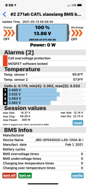
Needed to investigate this anomaly (didn’t think the voltage should have been over 13.4 or much closer). So I decided to turn the batteries off using the BMS. But did not turn off solar controllers breaker or Battery breaker. My mistake I think??
Returned to check on the next day late morning. Noticed on Victron app that solar controller #1 front was not showing up and turned breaker on and off and it popped back up on the screen. Voltage was back down where I thought it should be
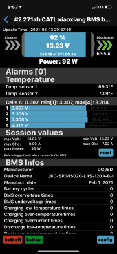
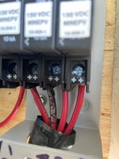
Went back later that day and #1 solar breaker was popped again and even after reset couldn't get #1 to show on Victron App. Didn't have time to mess with it so came back the next day. Took off cover on breakers and saw this
And this is my original setup of controllers
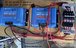
Here is what I think may have happened. I thought it was charging funny and didn’t have time to investigate so I used my bms to turn off charging to the batteries but I didn’t turn of the solar controllers or flip the solar breakers to off. The back panels were shaded by a building so it had no problems but the front panels had full sun and was trying to force that into batteries that were shut down. So going through the PV breaker into the solar controller then out of solar controller to battery breaker but the front battery wasn’t accepting it? That’s my guess at explaining it and why one breaker wire burnt and the other didn’t.
Does that sound like a plausible cause?
Why would there be a voltage discrepancy with the Victron BMV 13.52V(that is connected to the positive post of the batteries and neg to the load side of the shunt) and the meter 13.21V that is connected to the positive and negative post of the battery?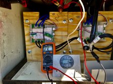
Any suggested improvements on my setup are greatly appreciated.
Changed my Xantrex sw3000 inverter to an AGM profile that with 2 stage charging with bulk/absorption@14.2v and float @13.45. It does not have a lithium profile or a custom profile. Do you guys see any problem with that setup?
Installed a victron DCDC 30A battery charger to replace the isolator on the RV to charge the start and house batteries. Confirmed that alternator was pushing out only 14.1v for charging of start batteries.
I installed 1120w of solar last year and chose to use two victron 100/50 solar controllers w/560w on each controller with room to expand. Pulled the MH out into the sun to see how my lithium’s would charge by solar. Had the Solar controllers set to float @ 13.4v. Turned on inverter and a floor fan and left overnight. Let charge the next day with solar and checked on later in the afternoon and had one battery bms report the following
Monitoring the batteries with Victron BMV712 and Overkill solar 120A BMS on both batteries.

Needed to investigate this anomaly (didn’t think the voltage should have been over 13.4 or much closer). So I decided to turn the batteries off using the BMS. But did not turn off solar controllers breaker or Battery breaker. My mistake I think??
Returned to check on the next day late morning. Noticed on Victron app that solar controller #1 front was not showing up and turned breaker on and off and it popped back up on the screen. Voltage was back down where I thought it should be

Went back later that day and #1 solar breaker was popped again and even after reset couldn't get #1 to show on Victron App. Didn't have time to mess with it so came back the next day. Took off cover on breakers and saw this

And this is my original setup of controllers

Here is what I think may have happened. I thought it was charging funny and didn’t have time to investigate so I used my bms to turn off charging to the batteries but I didn’t turn of the solar controllers or flip the solar breakers to off. The back panels were shaded by a building so it had no problems but the front panels had full sun and was trying to force that into batteries that were shut down. So going through the PV breaker into the solar controller then out of solar controller to battery breaker but the front battery wasn’t accepting it? That’s my guess at explaining it and why one breaker wire burnt and the other didn’t.
Does that sound like a plausible cause?
Why would there be a voltage discrepancy with the Victron BMV 13.52V(that is connected to the positive post of the batteries and neg to the load side of the shunt) and the meter 13.21V that is connected to the positive and negative post of the battery?


