diy solar

diy solar

Load side AC coupling, SA 15K and 18Kpv

GuyG

Solar Enthusiast
Joined
Feb 4, 2023
Messages
250
Location
MS
Two questions:

1. SolArk has made known its strong preference for AC coupling through the gen port as opposed to a load side sub panel input. EG4 does not address load side coupling on its 18Kpv, as far as I can tell. I’m attaching a shot of the manual dealing with AC coupling, which is not exactly a model of clarity, and says only that the AC coupling should be on the gen port.

My first question is whether the 18Kpv supports load side AC coupling at all. Seems like I remember someone saying it does, sort of. Maybe that it does, but cannot be used for charging, only AC. Can someone from EG4 or Lux clarify this?

2. Second question is about both inverters. Does the ~19-21 kw limit on AC coupling increase in a parallel configuration? That is, if two parallel inverters are handling a combined 35-40 Kw of DC, can they also take, say, a combined 25-35 kw of ac-coupled power too?

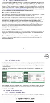
Here’s that page from the EG4:
 

Attachments

  • IMG_6095.jpeg
    IMG_6095.jpeg
    292.8 KB · Views: 26
I believe the 18Kpv is like the Solark in that it recommends using the Gen port for AC coupling.
 
Thanks FilterGuy.

Yes, SA (through its manual and excellent postings here by Carlos) has clearly explained its preference for the gen port as well as its reasons, and also the limitations if you choose to ac couple through a sub panel. It wouldn’t surprise me at all if EG4 says the same.

But that’s not my question. The first question is whether the 18Kpv supports load side AC coupling at all. I think it probably does, and can’t imagine why it wouldn’t. But its manual states in bold black letters “The existing solar system is connected to the inverter's GEN port.” Following that statement is a bunch of word salad, with no reference whatsoever to load side coupling or its limitations, if any.

The second question is about whether additional ac coupling beyond about 20kw is supported, if multiple inverters are in parallel. Neither SolArk nor EG4 has addressed this, AFAIK.

Answers to both of these questions is important to me for a system presently under design.
 
I’ll go into a little more detail about the system under design and why these questions are important.

The first phase of this system will start with at least two inverters deriving its PV from a ground array of 35-40 kw. Inverters and batteries will be in a central power shed and the power will be distributed to several structures.

One structure with a heavy demand (sometimes with 15-minute peaks of 48 kw) has a lot of roof but has shading problems. There, 10-15 kw of Microinverter panels would be helpful into that structure’s sub panels. Going into the gen port isn’t an option; that structure is over 100 feet from the power shed and its buried service conductor is already in place for many years, during which time a paved parking apron has been built. New trenching for cable back to the power shed for a few kw? No thanks. Besides, on most days 15kw of ac coupled power into that structure’s subpanel will likely be consumed at the structure itself without even feeding back to the hybrid inverters in the powershed.

Another structure, also over 100 feet from the power shed in the opposite direction and already fed by underground conductor, is a pool cabana. It has a smaller load, about 5 kw continuous (pool pumps for 80,000 gallon pool) with peak demand of 10kw or so. The cabana has roofing that would accommodate another 10-15 kw of panels, which could either be Microinverter or a Fronius grid tie into the pool sub panel. Again, laying new cable back to the gen port on the powershed inverters is a nonstarter.

If both of those rooftop systems were added, they would produce AC-coupled power of 20-30 kw, well above the stated limits for a single inverter. As mentioned earlier, during peak periods most of that power would normally be consumed at the structures where it is produced. But the facility curtails its operations outside of the summer months, at which time a good bit of that ac coupled power might in fact flow back to the central inverters through the load side.

There will be an interconnect agreement with the poco allowing sell back to the grid, so that is not a problem. But sell back is not the goal, or even desirable during the summer peak months when the consumption demand is particularly high (sometimes over a Mwh per day).

Future expansion will involve as many as four paralleled inverters with some additional PV arrays. It might also call for an additional array quite some distance from the power shed, making it attractive to have PV conductor voltages from that array even higher than what either SA or 18kpv allow. In that event a Fronius in the powershed could invert that power and feed it into the paralleled hybrids’ gen ports.

For example, we might end up with three paralleled hybrids in the power shed processing about 60 kw of regular PV, with 10-15 KW of load side AC through sub panels at each of two remote structures, plus an additional 15+ KW of AC from a Fronius connected to the gen ports of the paralleled hybrids.

I’m just looking for some definitive information about what these two inverter models can and cannot do with AC coupled power should that option be added to the basic system.
 
For the Sol-Ark 15k:
I'm guessing the 19k limit for AC Solar is based upon coming in the Gen Port, which has a 19k limit.
The Load port can pass 200 amps (48kW), so you should be able to, in theory, put that much AC solar through the Load port.

The risk you run is when grid is down. The most the Sol-Ark can send to the battery is about 14kW (assuming your battery can take that much), and it can't disconnect the Load port. So, if your micro-inverters don't drop production fast enough (frequency shifting), you could fry the Sol-Ark.

What I recommend is:
Main panel connected directly to the grid.
Each of your inverters (treating a set of micro-inverters as an inverter) connect to the Main Panel.
If the grid is down, then the inverter does what the inverter does (island, shut down, whatever).

Basically:
Grid -> Power Shed Main Panel
Main Panel -> Inverter in Shed
Main Panel -> Heavy Demand Structure
Main Panel -> Cabana

I don't understand why the existing line from the Heavy Demand Structure can't go into the Gen Port? Do you need more than 19kW to that stucture? If you can put the Heavy Demand Structure through the Load port, then you should be able to do it through the Gen Port.

If you need battery backup at the Heavy Demand Structure, then put a Sol-Ark there with batteries, and use TIGO Optimizers.
 
The risk you run is when grid is down. The most the Sol-Ark can send to the battery is about 14kW
Good point, which is sort of why I asked the parallel question. If one inverter can process 12.5 kw to the batteries for a short time while it curtails output from the Microinverters, why can’t three inverters process 37.5 kw?
 
I don't understand why the existing line from the Heavy Demand Structure can't go into the Gen Port?
The paralleled inverters will output from their load lugs all of their AC production plus grid passthrough into a combined power distribution panel. From there, six feeder circuits will carry power to various structures, two of which I’ve described. The feeder conductors already underground are (and will be) used for the main power feed to that structure. It’s 4/0 or 250, can’t remember which right now. Not gonna divert it from the load to the gen. And I’m not gonna propose that they trench along the existing feeder line just to add a cable run so that microinverter power can run 100 feet back to the gen port and then turn around to go right back to the structure from which it came.
 
Also, on the SolArk I’m fairly certain that if the grid goes down, it instantly starts frequency shift to curtail AC coupling. Not sure if the 18kpv does this the same way. Which is why I’m asking.
 
Also, on the SolArk I’m fairly certain that if the grid goes down, it instantly starts frequency shift to curtail AC coupling. Not sure if the 18kpv does this the same way. Which is why I’m asking.
When the grid goes down the 18Kpv will disconnect from the grid. If there is more energy being generated than the loads and batteries are taking, it will immediately start ramping down the MPPTs and frequency shift up to ramp down the AC coupling.
 
Not all AC coupling algorithms are the same and the only standards are the ones that determine how the GT inverter will respond to frequency shift. The biggest issue is how fast the AC coupled grid dependant inverter can ramp down. Some standards have delays built in and that is why changing the grid profile on the GT inverter can help.

The successful SolArk cases of AC coupling have large proportions of DC coupled solar. I presume that is because most DC coupled solar can be ramped down quicker. As far as the original question which @GuyG asked about the EG4, I think a lot depends on the dynamics of the system and how rapidly the loads change. Also keep in mind that this only matters when the grid is down. When the grid is up, the grid offers the ultimate buffer.
My theory about the use of the Gen Port for AC coupling is that someone must have concluded that it was better to have the ability to open a relay if the GT grid dependant inverter cannot be ramped down quickly enough.
 
Last edited:
Not all AC coupling algorithms are the same and the only standards are the ones that determine how the GT inverter will respond to frequency shift. The biggest issue is how fast the AC coupled grid dependant inverter can ramp down. Some standards have delays built in and that is why changing the grid profile on the GT inverter can help.
Interesting point. I started to argue that the standards define how the hybrid should implement the frequency shift but then realized that you are correct, the standards for UL cert only define how an inverter should react to frequency shift on the grid. My assumption (and you know what they say about assUme) is that the hybrid is designed to work with inverters that react to frequency shift as defined by the spec.
 
My assumption....... is that the hybrid is designed to work with inverters that react to frequency shift as defined by the spec.
Yes, and that algorithm is presumably different for every brand. That is why the answer to the question of @GuyG is not easy to answer. It depends a lot on the dynamics of the system and the relationship of the parts of the system and the variability of the loads.
 
I’m just looking for some definitive information about what these two inverter models can and cannot do with AC coupled power should that option be added to the basic system.
Due to the shading issues, I think you are right about thinking about micro inverters.
The nice thing about hooking AC coupled to the GEN input, the LP inverter will be able to switch off the AC coupling very fast without having to rely on phase/freq/voltage shaping. Since you basically will not be using hardly any of the PV inputs (if I read it correct) you might consider going to a more AC oriented setup with a bunch of Tesla Powerwall's in parallel. Costs will be a lot higher though.
 
I’m just looking for some definitive information about what these two inverter models can and cannot do with AC coupled power should that option be added to the basic system.
The high level answer conceptually is that the more DC coupled Solar you can have and the larger the battery pack will increase the amount of AC coupled solar that will work. Perhaps if you don't have unshaded roofs consider optimizers on the DC coupled solar.
 
Good point, which is sort of why I asked the parallel question. If one inverter can process 12.5 kw to the batteries for a short time while it curtails output from the Microinverters, why can’t three inverters process 37.5 kw?
3 inverters can send 3x the amount of excess power to the batteries. The problem case is when the batteries are near full and cannot take the full amount of excess power.

Putting a dump load on the generator input could solve the problem.
 
Since you basically will not be using hardly any of the PV inputs (if I read it correct)

No. As mentioned in the first post, there would be 35-40 KW of PV. The question is whether the 18kpv inverter supports additional power via AC coupling on the load side. And if so, how much in a parallel configuration.
 
@Carlos_Sol-Ark posted an excellent explanation in another thread.

 
And Gilbert posted this in a different thread:

ac couple on the EPS Load wont charge your battery after supporting your house load, it will sell to the grid the rest. Unless your inverter is not connected to the grid…
With ac couple on the Gen port, first it will support your house load and 2nd charge your battery and 3rd when your battery is full it will sell to the grid…
 
But still no definitive answers from Signature/EG4 to either of my questions.
 
But still no definitive answers from Signature/EG4 to either of my questions.
I look at it from two perspectives. Theorectically the only limit on AC coupling when the grid is up is the throughput capacity of the Inverter. When the grid is down the limit on AC coupling becomes an issue that involves battery pack size and the grid forming inverter firmware's ability to use frequency Watt to control the AC coupled GT inverters.
There is also a scenario which some call AC coupling but in which the grid dependant inverter is not actually coupled through the grid forming inverter and is connected directly to the main service panel. Clearly in this scenario there is no functionality when the grid is down but the only limit on AC capacity is the utility infrastructure to handle backfeed.
So depending on the scenario, the answer to your question will be different. Based on the title of this thread, the load side AC coupling assumes the grid dependant inverters is connected through the grid forming inverter, shich is presumably the load side.
 
Last edited:
No. As mentioned in the first post, there would be 35-40 KW of PV. The question is whether the 18kpv inverter supports additional power via AC coupling on the load side. And if so, how much in a parallel configuration.
LXP recommend connecting ac couple to the Gen Port, max is (90A ac)...
 
Last edited:

diy solar

diy solar
Back
Top