Ok this makes sense. I was connecting the charger to the battery permanently. I didn't expect to have to charge a capacitor like connecting an inverter. Can this sparking damage the charger?Well the trick is either to Precharge the charger output capacitor through a resistor OR ... simply have a breaker (which you would need anyways !) on the output of the charger.
1. Open the breaker on the DC side so charger/battery are isolated from each other
2. Connect charger to 240VAC
3. With DC output breaker in OPEN position, connect cable to battery (IDEALLY you should leave that permanently connected anyway ... you have a switch/breaker as stated before)
4. Charger output voltage rises to 53-57 VDC
5. There is now only a ~ 5 VDC voltage difference between charger and battery (i.e. ACROSS the DC output breaker)
6. Close the DC output breaker
That way you won't have any sparking.
About the yellow "triangle" ... Are you talking about the yellow LED on the charger flashing ? I leave the charger permanently connected to the battery and my understanding is that the charger flashes the yellow LED if the battery voltage (i.e. output voltage of the rectifier) rises ABOVE the setpoint.
Meaning basically that the rectifier is BLOCKED and the output current is zero (or below a given threshold).
For me this is the case if I set the charger output voltage to 52VDC and there is some solar panel production during the day, causing the output voltage / battery voltage to go above that (say 53 VDC). Since the charger is NOT bidirectional (it will NOT take power from the battery and send it to the grid / generator), and it cannot deliver any current without "violating" the output voltage set-point, from its point of view it's a warning I guess.


You are using an out of date browser. It may not display this or other websites correctly.
You should upgrade or use an alternative browser.
You should upgrade or use an alternative browser.
Looking for 48V Battery Charger
- Thread starter silverstone
- Start date
Brilliant, this makes sense regarding the sparking and connecting it up. The battery bank is only half charged. It's at 52.8v.Well the trick is either to Precharge the charger output capacitor through a resistor OR ... simply have a breaker (which you would need anyways !) on the output of the charger.
1. Open the breaker on the DC side so charger/battery are isolated from each other
2. Connect charger to 240VAC
3. With DC output breaker in OPEN position, connect cable to battery (IDEALLY you should leave that permanently connected anyway ... you have a switch/breaker as stated before)
4. Charger output voltage rises to 53-57 VDC
5. There is now only a ~ 5 VDC voltage difference between charger and battery (i.e. ACROSS the DC output breaker)
6. Close the DC output breaker
That way you won't have any sparking.
About the yellow "triangle" ... Are you talking about the yellow LED on the charger flashing ? I leave the charger permanently connected to the battery and my understanding is that the charger flashes the yellow LED if the battery voltage (i.e. output voltage of the rectifier) rises ABOVE the setpoint.
Meaning basically that the rectifier is BLOCKED and the output current is zero (or below a given threshold).
For me this is the case if I set the charger output voltage to 52VDC and there is some solar panel production during the day, causing the output voltage / battery voltage to go above that (say 53 VDC). Since the charger is NOT bidirectional (it will NOT take power from the battery and send it to the grid / generator), and it cannot deliver any current without "violating" the output voltage set-point, from its point of view it's a warning I guess.
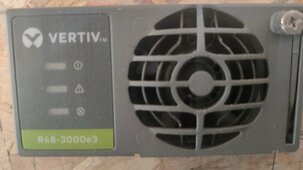
The orange flashin light is on the vertive charger.
Ah, that's an alarm indicator (here is the datasheet). It can happen as @silverstone said if the battery voltage is higher, but also when you're at max power I believe. When you're connected to the generator, and charging the battery it should go away once you're getting to the set voltage (i.e., less power going in).
I understand. I have wired the generator into the house now so I'm just about to crank the handle and start her up. Happy days. I have it wired straight to the battery but I'll send it through the BMS later for more fun! Yahoo! Thanks for all the info folks.Ah, that's an alarm indicator (here is the datasheet). It can happen as @silverstone said if the battery voltage is higher, but also when you're at max power I believe. When you're connected to the generator, and charging the battery it should go away once you're getting to the set voltage (i.e., less power going in).
silverstone
Solar Enthusiast
- Joined
- May 3, 2022
- Messages
- 1,041
Rated output current is 62.5ADC according to datasheet.The output of the charger is probably limited to 50 amps. My generator wont be working at 80% probably less than 60% but its an old crank handle Lister/Peter so I'll go gently first to see how things develope.
Why do you claim that it's limited to 50 ADC ? Did you program that limit ?
Maybe you just didn't set the output voltage high enough to reach that current. You have some voltage drop across cables as well as the ESR (Equivalent Series Resistance) of your Battery Cells.
Roughly at 50A I'd be looking at least at 1-1.5 VDC extra, although that depends on many things.
The charger will anyway go into current limitation, so you can try to set the setpoint to 58V for a short test and see if it jumps to 50 ADC or 62.5 ADC.
The other explanation is that you inverter has some steady-state power consumption. Mine has 300-400W. Plus the inverter's AC load of course. So some of the current of your charger does NOT flow into the battery but rather goes "straight into the inverter".
Indeed I believe my output voltage isnt set high enough. It was set at 53.5v iirc, you can choose this when buying the unit. Id like it to be higher but I dont know how to program through the CAN bus. I can see where the 2 wires connect in but I'll have to look up the ins and outs of programing it. I assume I have to make a cable that connects to my laptop and learn how to do it from there.
silverstone
Solar Enthusiast
- Joined
- May 3, 2022
- Messages
- 1,041
Remind me... Do you have the Emerson R48-3000e?Indeed I believe my output voltage isnt set high enough. It was set at 53.5v iirc, you can choose this when buying the unit. Id like it to be higher but I dont know how to program through the CAN bus. I can see where the 2 wires connect in but I'll have to look up the ins and outs of programing it. I assume I have to make a cable that connects to my laptop and learn how to do it from there.
In that case @upnorthandpersonal github repository will do the trick for you.
I am using essentially the same code for my controller, plus some BASH interfacing, systemd servicing / cron to semi-automatically update the setpoint based on electricity rates.
Right now it's "open loop" but I plan to also do closed loop as soon as I get the chargers readings and the jk bms reliably
 .
.There are a bit more instruction in my repo about the pitfalls of the programming etc.
You might not need all of the stuff, but you could get a few tips
GitHub - luckylinux/solar-controller: Solar Controller Tools
Solar Controller Tools. Contribute to luckylinux/solar-controller development by creating an account on GitHub.
 github.com
The script from @upnorthandpersonal is also fine if you are into programming, but it's quite bare-bones (no offence @upnorthandpersonal ).
You need to manage the looping yourself, unless you want to set a PERMANENT voltage setpoint & current limit and NEVER touch that again.
Right now, with my script, you setup the script and an excel lookup table each day, and it can do the variable voltage.
Or you can use my code as inspiration and setup just a looping with a fixed value "ad-hoc".
It's just important that you implement a way to make sure the service and looping starts automatically at boot in case you reboot etc.
Otherwise it will fall-back to it's pre-programmed PERMANENT values.
Last edited:
I have the Vertive R48 3000e3.Remind me... Do you have the Emerson R48-3000e?
In that case @upnorthandpersonal github repository will do the trick for you.
I am using essentially the same code for my controller, plus some BASH interfacing, systemd servicing / cron to semi-automatically update the setpoint based on electricity rates.
Right now it's "open loop" but I plan to also do closed loop as soon as I get the chargers readings and the jk bms reliably
There are a bit more instruction in my repo about the pitfalls of the programming etc.
You might not need all of the stuff, but you could get a few tips

GitHub - luckylinux/solar-controller: Solar Controller Tools
Solar Controller Tools. Contribute to luckylinux/solar-controller development by creating an account on GitHub.
The script from @upnorthandpersonal is also fine if you are into programming, but it's quite bare-bones (no offence @upnorthandpersonal ).
You need to manage the looping yourself, unless you want to set a PERMANENT voltage setpoint & current limit and NEVER touch that again.
Right now, with my script, you setup the script and an excel lookup table each day, and it can do the variable voltage.
Or you can use my code as inspiration and setup just a looping with a fixed value "ad-hoc".
It's just important that you implement a way to make sure the service and looping starts automatically at boot in case you reboot etc.
Otherwise it will fall-back to it's pre-programmed PERMANENT values.
I dont know what open and closed loops are. Id probably go with the simpler option and use a permanent voltage setpoint and current limit. Something that would draw enough amps from the generator up to around 80% SOC. If I forgot to switch off the generator the BMS should protect the bank.Remind me... Do you have the Emerson R48-3000e?
In that case @upnorthandpersonal github repository will do the trick for you.
I am using essentially the same code for my controller, plus some BASH interfacing, systemd servicing / cron to semi-automatically update the setpoint based on electricity rates.
Right now it's "open loop" but I plan to also do closed loop as soon as I get the chargers readings and the jk bms reliably
There are a bit more instruction in my repo about the pitfalls of the programming etc.
You might not need all of the stuff, but you could get a few tips
GitHub - luckylinux/solar-controller: Solar Controller Tools
Solar Controller Tools. Contribute to luckylinux/solar-controller development by creating an account on GitHub.
The script from @upnorthandpersonal is also fine if you are into programming, but it's quite bare-bones (no offence @upnorthandpersonal ).
You need to manage the looping yourself, unless you want to set a PERMANENT voltage setpoint & current limit and NEVER touch that again.
Right now, with my script, you setup the script and an excel lookup table each day, and it can do the variable voltage.
Or you can use my code as inspiration and setup just a looping with a fixed value "ad-hoc".
It's just important that you implement a way to make sure the service and looping starts automatically at boot in case you reboot etc.
Otherwise it will fall-back to it's pre-programmed PERMANENT values.
I'm also looking to get a bigger generator that would connect into the Growatt and turn on automatically running the house and charge the batteries. I would continue to use the small swing handle lister generator most of the time but if my wife was alone the larger generator would kick in at 20% SOC. Anyhow thanks for the help I appreciate it

HarryN
Solar Enthusiast
If you are looking for a simple way to pre-charge, just use a small solar panel with a Voc similar to your nominal battery voltage.
Connect it to the system via a breaker and turn it on for a few minutes.
I made this little test fixture just to demonstrate the concept for 12 volt. Very easy and nearly bullet proof.

 diysolarforum.com
Connect it to the system via a breaker and turn it on for a few minutes.
I made this little test fixture just to demonstrate the concept for 12 volt. Very easy and nearly bullet proof.
Small test fixture
Sometimes it is easier to show people things in photos than to describe them. So I made a little test fixture from left over parts, nothing fancy. In this case, some people asked about methods of dealing with pre-charging the capacitors on the input stage of inverters, and I had suggested that...
diysolarforum.com
Thanks for that HarryNIf you are looking for a simple way to pre-charge, just use a small solar panel with a Voc similar to your nominal battery voltage.
Connect it to the system via a breaker and turn it on for a few minutes.
I made this little test fixture just to demonstrate the concept for 12 volt. Very easy and nearly bullet proof.
Small test fixture
Sometimes it is easier to show people things in photos than to describe them. So I made a little test fixture from left over parts, nothing fancy. In this case, some people asked about methods of dealing with pre-charging the capacitors on the input stage of inverters, and I had suggested that...
Similar threads
- Replies
- 1
- Views
- 105